189 Programmable Hardware Manual (PHM)
© Tibbo Technology Inc.
Ethernet status LED, connected to the EY line of
the EM1000
Signal strength bar, #1 (the lowest level).
Signal strength bar, #5 (the highest strength).
Note 1. This resistor's value is 0 because there is another resistor connected in
series with the EM1000's I/O line and located on the NB10x0 board.
Note 2. This LED is controlled through an additional "LED bar" circuit, described in
the External LED Control topic.
Note 3. Further information on status LEDs can be found in Status LEDs.
5.3.3.2
LB1001
The LB1001 is a standard LED board supplied with IB100x interface boards. The LEDs
on the board are arranged into 4 groups, each group consisting of one green and
one red LED. Although the LB1001 connects to IB100x boards, the actual control of
the LEDs is effected from the EM1000 module installed on the NB10x0 board. To turn
a certain LED on, set the corresponding general-purpose I/O (GPIO) line LOW. The
line has to be configured as output. I/O line control is described in detail in the
documentation for the "I/O" (io.) object found inside the TIDE, TiOS, Tibbo BASIC,
and Tibbo C Manual. These LED's can also be used to play patterns generated by
the ("pattern") .pat object. Correct "mapping" is required for this to work -- see
object documentation for details.
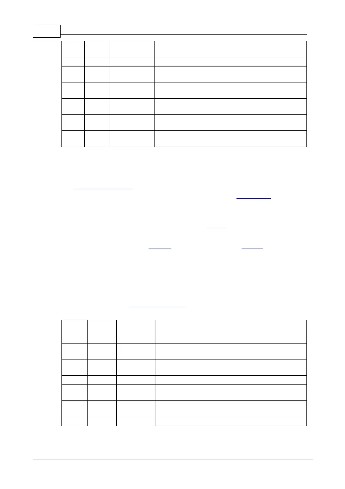
Table below shows LED arrangement for this board. LED numbers correspond to the
numbers shown on the mechanical drawing for the LB1001.
Controlled by the GPIO24 of the EM1000 (pin 46
on the interboard connector header).
Controlled by the GPIO25 of the EM1000 (pin 44
on the interboard connector header).
Controlled by the GPIO26 of the EM1000 (pin 42
on the interboard connector header).
Controlled by the GPIO27 of the EM1000 (pin 40
on the interboard connector header).
 Loading...
