263 Programmable Hardware Manual (PHM)
© Tibbo Technology Inc.
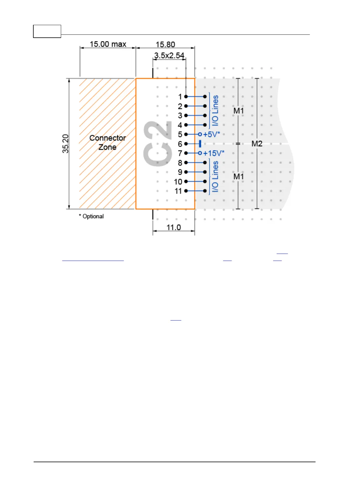
Pins 1-4 and 8-11 are I/O lines that connect directly to the I/O lines of two
adjacent "M" sockets. A single C2 may connect to one M2 Tibbit or two M1 Tibbits.
Pin 5 is the +5V power pin. Most C2 devices only house connectors and do not
require any power. Still, we are sure there will be uses for this power pin in the
future.
Pin 6 is the ground pin.
Pin 7 is the +15V power pin. Again, this is reserved for the future use.
Since C2 devices have dedicated ground and power lines they are not dependent on
"M" Tibbits for power and ground, as C1s are. There is no provision for connecting -
15V power though. If any C2 device needs -15V then this must be supplied by the
adjacent "M" device.
 Loading...
