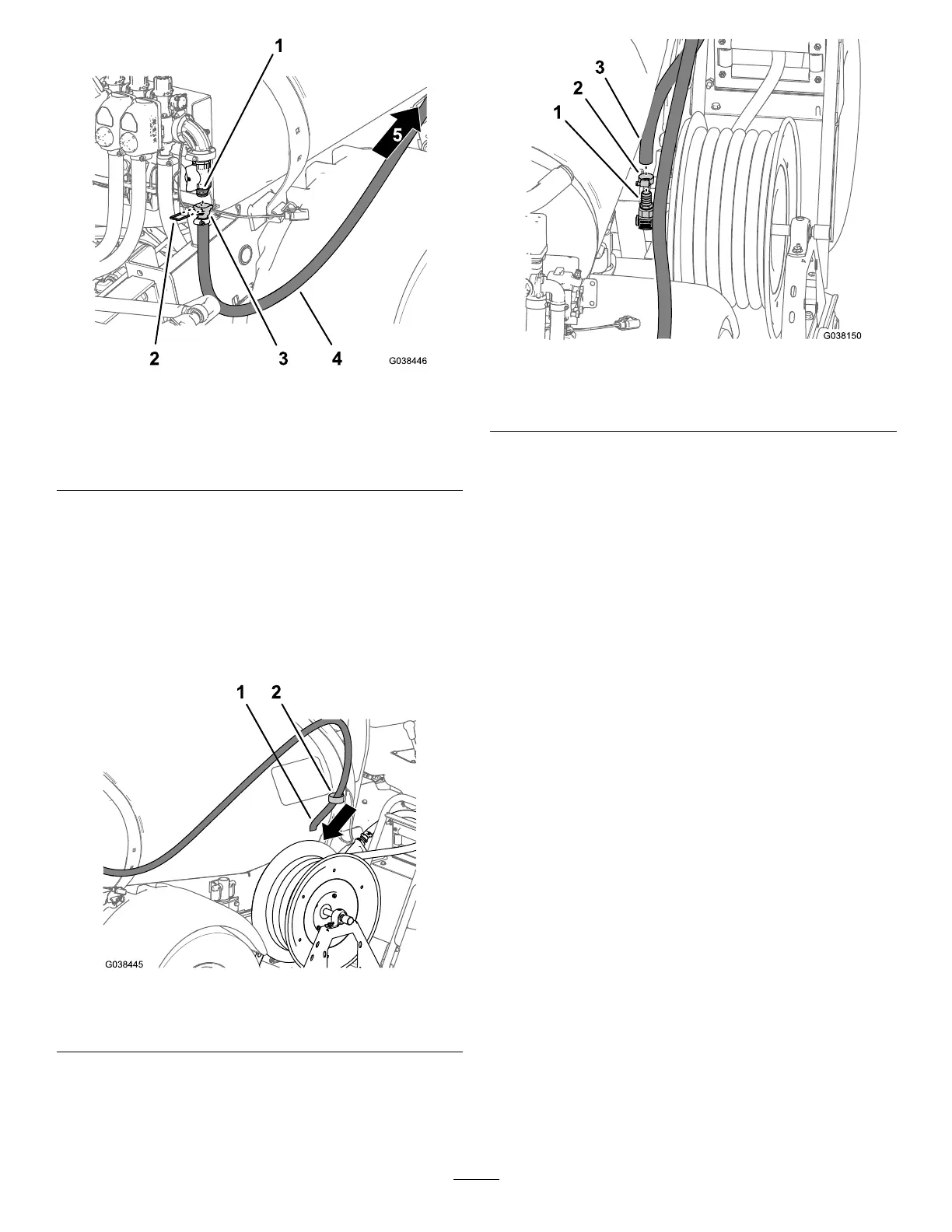
Figure96
1.Quick-connecttting
(angeshutoffvalve)
4.Hose—1.3x180cm(1/2
x83inches)
2.Retainer
5.Frontofthemachine
3.Straightbarbedtting
3.Securethestraightbarbedttingandthequick-connect
tting(Figure96)withtheretainerthatyouremovedin
step3ofInstallingtheShutoffValvefortheOptional
SprayGunKitortheElectricHoseReelKit(page42).
4.Routethesupplyhoseforwardalongthesprayertank
towardthehosereel(Figure96).
5.Assembletheinlethosethroughthesupportclampat
theforwardstrapofthesprayertank(Figure97).
Figure97
1.Hose—1.3x180cm(1/2
x83inches)
2.Supportclamp
6.Assemblethesupplyhoseontothebarbedttingatthe
inletofthehosereel(Figure98),andsecurethehose
withahoseclamp13to32mm(1/2to1-1/4inches).
Figure98
1.Barbedtting(inletswivel)3.Supplyhose(hosereel)
2.Hoseclamp
45