E6582062
2. Installation and wiring 2-50
2
9
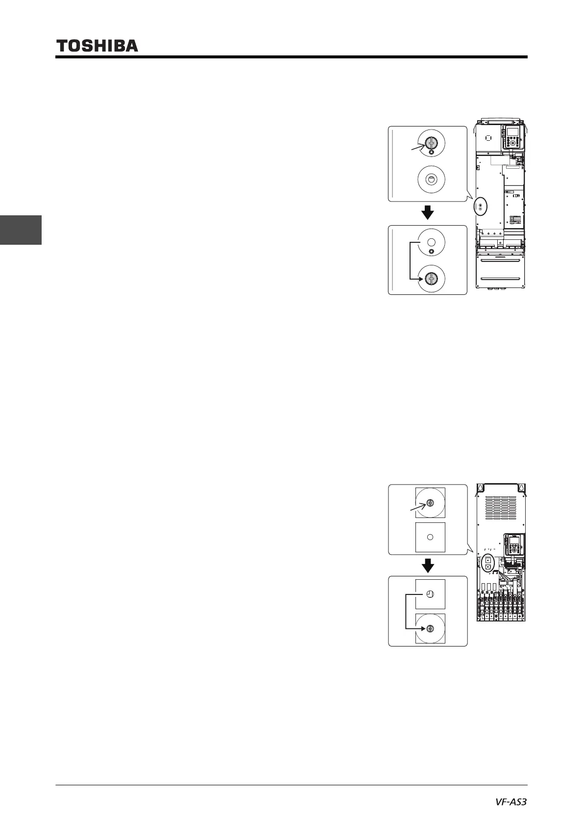
■ With frame size A5
VFAS3-2220P to 2370P, VFAS3-4450PC to 4750PC
1 Remove the front cover.
For how to remove, refer to [2. 2. 3].
2 Remove the screw for switching of grounding capacitor from
the position of the grounding mark and tighten it to the posi-
tion of the non-grounding mark.
The grounding capacitor is disconnected.
3 To recover the shipping state, remove the screw(s) for
switching of grounding capacitor and tighten it/them to the
screw hole in the position of the grounding mark.
The grounding capacitor is connected and grounded.
4 After switching, mount the front cover.
For how to mount, refer to [2. 2. 3].
For frame size A6, A7 and A8, grounding capacitor is set to small (non-grounding mark side).
To comply with EMC directive, switch the capacitance into large (grounding mark side) accord-
ing to the procedure below.
■ With frame size A6
VFAS3-2450P, 2550P, VFAS3-4900PC to 4132KPC
Gounding capacitor is set to small (non-grounding mark side). To comply with EMC directive, switch
the capacitance into large (grounding mark side) according to the procedure below.
1 Remove the front cover and the transparent cover inside
(transparent resin).
For how to remove, refer to [2. 2. 4].
2 Remove the screw for switching of grounding capacitor from
the position of the non-grounding mark and tighten it to the
position of the grounding mark.
The grounding capacitor's capacity is increased.
3 To recover the shipping state, remove the screw(s) for
switching of grounding capacitor and tighten it to the screw
hole in the position of the non-grounding mark.
The grounding capacitor's capacity is recovered.
4 After switching, mount the transparent cover and the front cover in this order.
For how to mount, refer to [2. 2. 4].
Screw
Grounding
Non-
grounding
Capacity small
Capacity
large
Screw

 Loading...


