E6581158
H-9
8
(Continued)
Item displayed
Key
operated
LED
display
Communi-
cation No.
Description
Integral input
power
M FE76
The integrated amount of power (kWh) supplied to
the inverter is displayed.
(0.01=1kWh, 1.00=100kWh)
Integral output
power
J
FE77
The integrated amount of power (kWh) supplied
from the inverter is displayed.
(0.01=1kWh, 1.00=100kWh)
Rated current C FE70
The inverter rated current (A) at the occurrence of
a trip is displayed.
Past trip 1
QR ⇔
FE10 Past trip 1 (displayed alternately)
Past trip 2
QJ ⇔
FE11 Past trip 2 (displayed alternately)
Past trip 3
QR ⇔
FE12 Past trip 3 (displayed alternately)
Past trip 4
PGTT ⇔
FE13 Past trip 4 (displayed alternately)
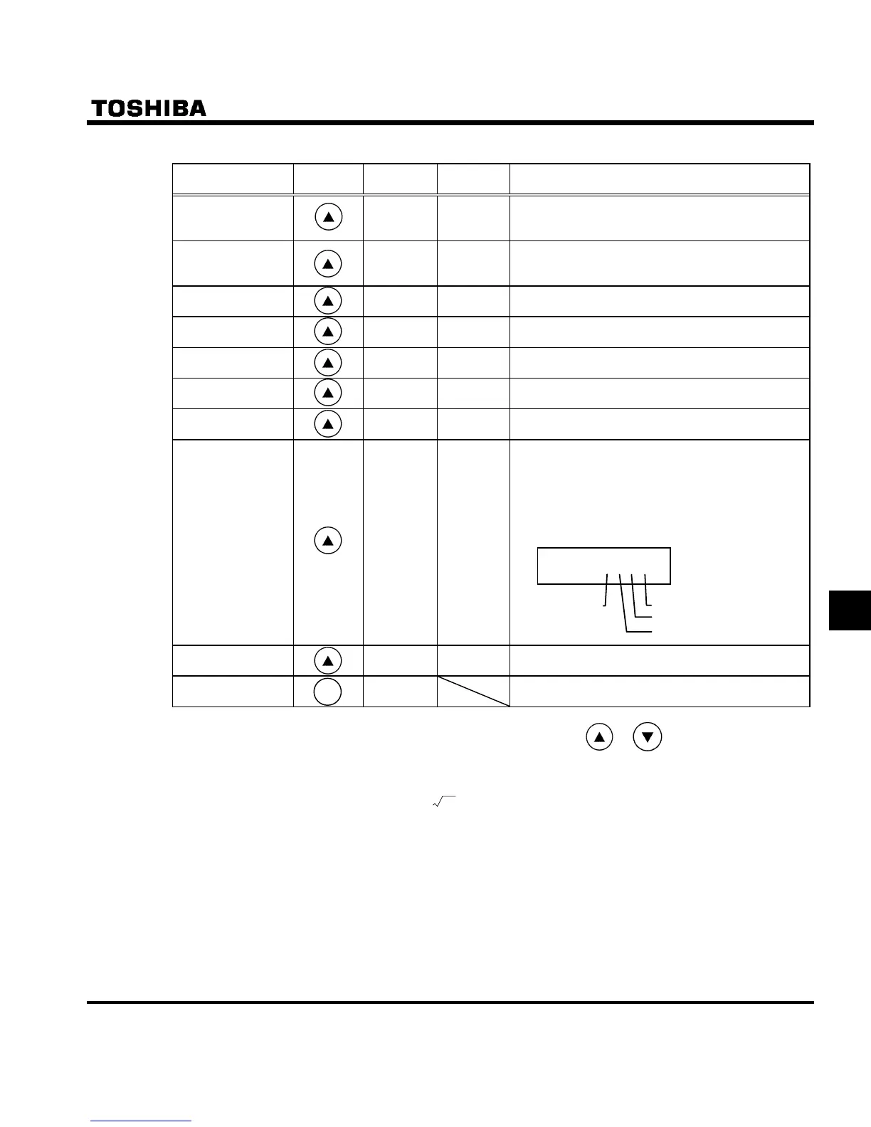
Life alarm infor-
mation
O ___K
FE79
The ON/OFF status of each of the cooling fan, cir-
cuit board capacitor, main circuit capacitor or life
alarm of cumulative operation time is displayed in
bits.
ON:
OFF: _
Cumulative opera-
tion time
V
FE14
The cumulative operation time is displayed.
(0.01=1 hour, 1.00=100 hours)
Default display
mode
QR
The cause of the trip is displayed.
Note 1: Items displayed when a trip occurs can be changed by pressing or key.
Note 2: You can switch between % and A (ampere)/V (volt), using the parameter H (current/voltage unit
selection).
Note 3: The input (DC) voltage displayed is 1
2
times as large as the rectified d.c. input voltage.
Note 4: The number of bars displayed varies depending on the setting of H (analog input/logic input func-
tion selection). The bar representing VIA or VIB is displayed only when the logic input function is as-
signed to the VIA or VIB terminal, respectively.
If H = : Neither the bar representing VIA nor the bar representing VIB is displayed.
If H = or : The bar representing VIA is not displayed.
The bar representing VIB is displayed.
If H = or : Both the bar representing VIA and VIB are displayed.
Note 5: The number of bars displayed varies depending on the setting of H (logic output/pulse train output
selection). The bar representing the OUT-NO terminal is displayed only when logic output function is as-
signed to it.
O ___K
Coolingfan
Cumulative
operation
time
Control circuit board capacitor
Maincircuitcapacitor
Note 7
Note 7
Note 7
Note 7
Note 8
Note 9
MO
MOMO
MODE
DEDE
DE

 Loading...


