E6581158
J-11
10
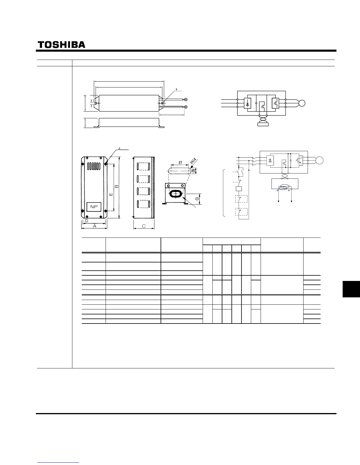
Devices External dimensions and connections
Braking
resistor
The resistances in the Rating column are combined resistances. The numeric values inside parentheses refer to the composi-
tions of resistors (resistance of each resistor x number of resistors).
Dimensions (mm)
Model Rating Inverter type
ABCDEG
External dimensions and
connections
Approx.
weight
(kg)
PBR-2007
120W-200Ω
VFS11-2002 ∼ 2007PM
VFS11S-2002 ∼ 2007PL
PBR-2022
120W-75Ω
VFS11-2015, 2022PM
VFS11S-2015, 2022PL
PBR-2037
120W-40Ω
VFS11-2037PM
42 182 20 4.2 172 - A and C 0.28
PBR3-2055
240W-20Ω (40Ω×2P)
VFS11-2055PM 320 115 50 4
PBR3-2075
440W-15Ω (30Ω×2P)
VFS11-2075PM 4.5
PBR3-2110
660W-10Ω (30Ω×3P)
VFS11-2110PM 5
PBR3-2150
880W-7.5Ω (30Ω×4P)
VFS11-2150PM
120
350 190
110 23 0
150
B and D
5.5
PBR-2007
120W-200Ω VFS11-4004 ∼ 4022PL
PBR-4037
120W-160Ω
VFS11-4037PL
42 182 20 4.2 172 - A and C 0.28
PBR3-4055
240W-80Ω (160Ω×2P)
VFS11-4055PL 320 115 50 4
PBR3-4075
440W-60Ω (120Ω×2P)
VFS11-4075PL 4.5
PBR3-4110
660W-40Ω (120Ω×3P)
VFS11-4110PL 5
PBR3-4150
880W-30Ω (120Ω×4P)
VFS11-4150PL
120
350 190
110 23 0
150
B and D
5.5
Note1: Use the same type of braking resistor of VFS11-2002 ∼ 2007PM for those of VFS11-4004 ∼
4022PL.
Note2: The data in Rating above refer to the resultant resistance capacities (watts) and resultant re-
sistance values (ȍ).
The numeric values inside parentheses refer to the internal compositions of resistors.
VF
-
S11
Fig. C
Fig. A
Fig. B
R
S
U
V
IM
T
B
C
A
E (Installation dimension)
4.2
D (Installation dimension)
500
(Lead wire length)
PA
Braking resistor
Power source
PB
W
4- 5 holes
Earth terminal
(M5)
Wire opening
(Installation
dimension)
(Installation dimension)
VF
-
S11
Fig. D
IM
U
V
W
PA/ +
PA
PB
PB
TH2
TH1
Braking resistor
Do not fail to connect to the operation circuit
R
S
T
MC
MC
E
E
ON
OFF
FLB
FLC
TH1
TH2
Power source
(Note 1)
Fig. C

 Loading...


