UNIT SETUP
Confi guring Controller Settings
FMS-1650
TRIATEK reserves the right to change product specifications without notice.
- 11 -
the user is next prompted for the Input Channel to use for analyzing
the relay setpoints. While relay output 1 uses Analog Input 1 by
default, it may be remapped to any one of the four universal analog
inputs (AI-2 through AI-4) or either of the two dedicated thermistor
inputs (TI-1 and TI-2). After selecting the desired input channel, the
user is next prompted for high and low relay setpoints for the current
isolation mode.
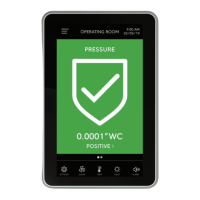
The high setpoint determines the threshold at which the alarm relay
gets activated if in direct acting mode, or gets deactivated if in reverse
acting mode. The low setpoint determines the threshold at which the
alarm relay gets deactivated if in direct acting mode, or gets activated
if in reverse acting mode. After specifying the high and low setpoints,
the user is prompted for the acting mode and delay associated
with the alarm relay. In direct acting mode, the alarm relay will be
activated when the sensor input exceeds the high setpoint, and will
be deactivated when the sensor input falls below the low setpoint. In
reverse acting mode, the alarm relay will be deactivated when the
sensor input exceeds the high setpoint, and will be activated when the
sensor input falls below the low setpoint. The alarm relay delay may
be up to 180 seconds, or three minutes, in duration.
If Isolation Mode is selected as the trigger mode for the alarm relay,
the user is next prompted to select whether the alarm relay should
activated or deactivated for each mode of isolation. Next, the user
is prompted for the acting mode and delay to be associated with the
alarm relay. If the FMS-1650 has been configured for a door switch
with a delay setting greater than zero, then the door switch delay will
count down before the alarm relay delay will begin counting down.
Otherwise, the alarm relay delay will begin counting down immediately
after the trigger condition is achieved, and the alarm relay will activate
or deactivate when the timer expires, depending on the acting mode
selected for the alarm relay. Isolation Mode is not available as a
selectable option, and will not be accepted if it is selected. This option
may be made available in a future firmware release. Contact the
factory for details.
If Occupancy Mode is selected as the trigger mode for the alarm relay,
the user is next prompted to select whether the alarm relay should
activated or deactivated for the two states of occupancy. Next, the
user is prompted for the acting mode and delay to be associated with
the alarm relay. If the FMS-1650 has been configured for a door switch
with a delay setting greater than zero, then the door switch delay will
count down before the alarm relay delay will begin counting down.
Otherwise, the alarm relay delay will begin counting down immediately
after the trigger condition is achieved, and the alarm relay will activate
or deactivate when the timer expires, depending on the acting mode
selected for the alarm relay. Occupancy Mode is not available as a
selectable option, and will not be accepted if it is selected. This option
may be made available in a future firmware release. Contact the
factory for details.”
Adjusting the PID Loop Settings
When the FMS-1650 is configured to use analog output 1 for closed-
loop control applications, the proportional, integral, and derivative
constants that determine the performance and characteristics of the
control scheme may be specified using the PID Loop Setup option on
the Controller Setup menus. Selecting this option invokes the PID
Loop Settings configuration screen as shown in Figure 16, where
the user can fine-tune the PID constants to be used by the closed-
loop control scheme for analog output 1. These three dimensionless
constants may vary from zero to 100 using the three sliders on the
configuration screen. See the PID Tutorial in the appendix at the end
of this document for more information on fine-tuning the PID constants
for a specific application.
Figure 15. High alarm
setpoint for positive
isolation mode may
be specified at this
configuration popup
screen.