SYSTEM SETUP
Confi guring Secondary Analog Inputs
FMS-1650
TRIATEK reserves the right to change product specifications without notice.
- 23 -
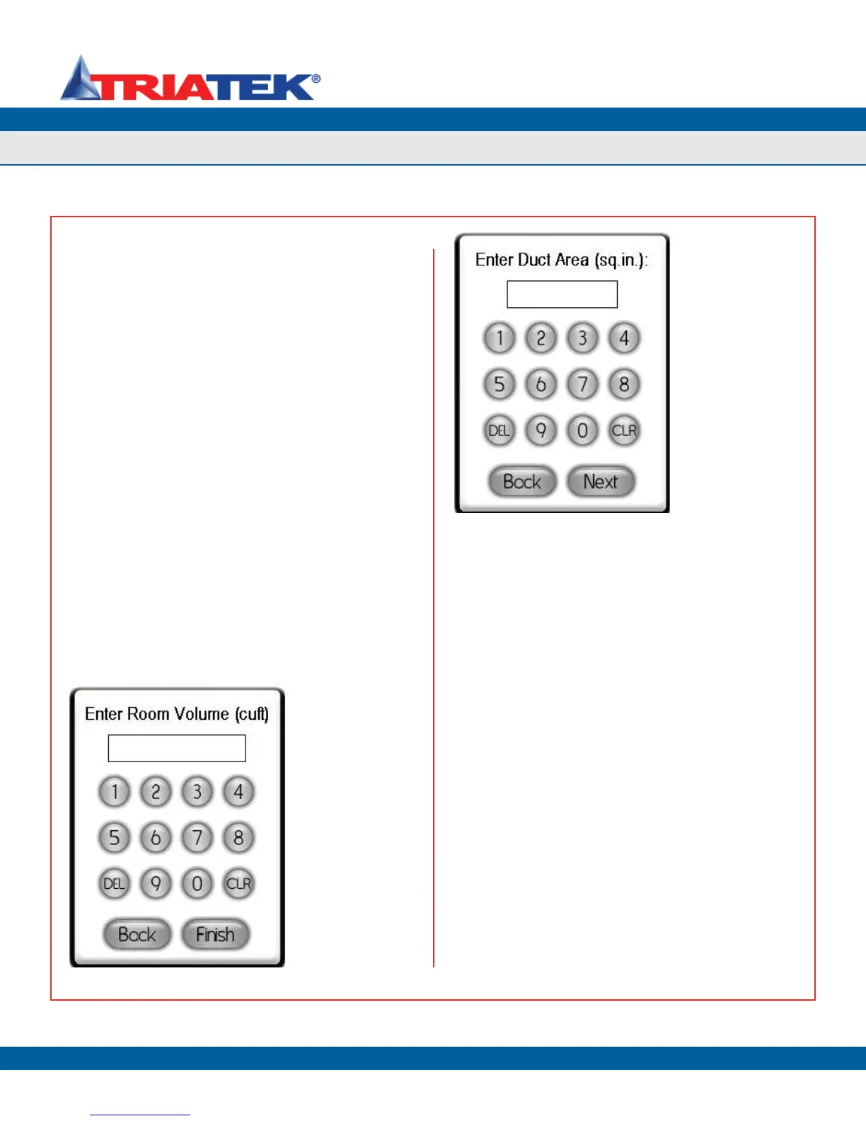
After specifying the duct cross-sectional area, click the Next button
to specify a K-factor for the specific sensor being used to input flow.
The default value for this K-factor is 1.0, but may be provided by the
manufacturer of the sensor to serve as a correction factor for the actual
output of that particular sensor unit. If no K-factor is available, this
value should be left at the default of 1.0.
Clicking the Next button invokes the Analog Input x Settings
configuration screen as shown in Figure 41, where the user may
specify whether or not air changes should be calculated and displayed
on the main screen, as well as the range of the input signal (voltage
or current) for the air flow sensor. If the air changes have been
selected for display, the user is prompted to enter the room volume in
cubic feet at the Enter Room Volume configuration screen shown in
Figure 42. The room volume is required to calculate the real-time air
change rate based on the flow input signal. To calculate the volume
of a rectangular room in cubic feet, multiply the length of the room by
the width and the height. For irregular shaped rooms, the volume will
have to be determined by breaking the room up into multiple smaller
rectangular areas and summing the individual volumes to calculate the
total room volume in cubic feet. Otherwise, an approximation may be
specified for the room volume. This volume may also be fine-tuned to
increase the accuracy of the displayed air change rate according to the
actual volumetric flow offset of the room.
If air changes have been selected for display and the flow
measurement device is an actual air flow sensor, then clicking the
Next button invokes the configuration screen shown below in Figure
42, which allows the user to specify the volume of the room being
monitored. The room volume is required to calculate the air change
rate.
Setting up Analog Inputs for Humidity
The FMS-1650 can be configured to measure and display humidity
in real-time using readily available sensors from BAPI® and other
manufacturers. To configure one of the secondary analog inputs for
humidity measurement, select Humidity from the Select Input Type
configuration screen (Figure 44) and click the Next button. The Analog
Input x Settings configuration screen shown in Figure 45 appears,
allowing the user to select the engineering units and voltage or current
input range for the connected sensor.
If the humidity input is being utilized for a humidity control scheme,
then clicking the Next button at the popup shown in Figure 45 invokes
the setpoint entry configuration screen shown in Figure 46 where the
user may enter a target humidity setpoint. The humidity input must
also be mapped to one of the analog outputs that has been configured
for PID control mode.
Figure 42. The room
volume in cubic feet
should be entered here
to allow the air change
rate to be calculated.
Figure 43. To
allow velocity or
velocity pressure
measurements to be
converted to flow, the
duct area is required in
square inches.