SYSTEM SETUP
FMS-1650
TRIATEK reserves the right to change product specifications without notice.
- 29 -
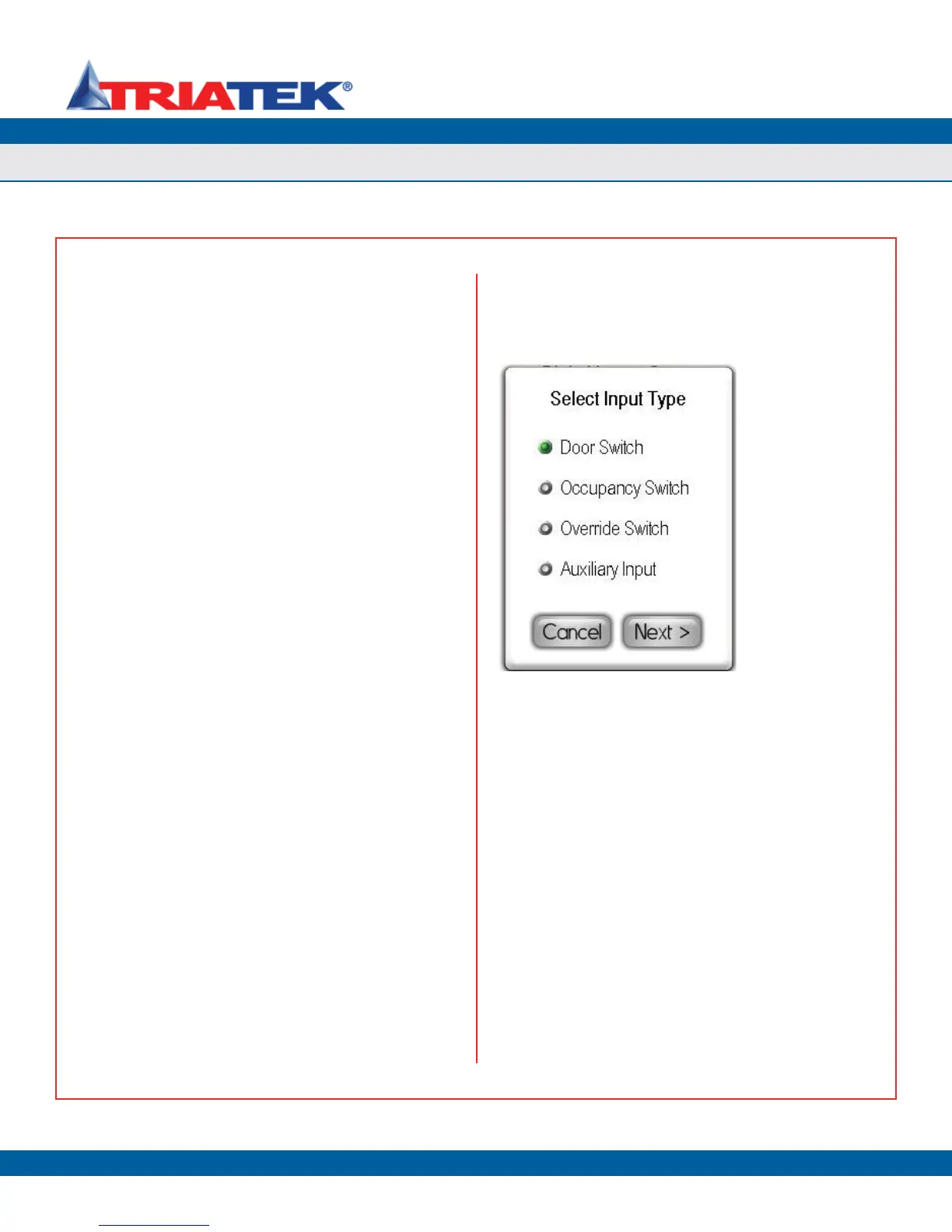
Selecting one of the secondary digital inputs from the Digital Inputs
Setup menu invokes the Select Input Type configuration popup as
shown in Figure 54. The user may select the operating mode and
polarity for this digital input resource. The selection between active-
high and active-low mode for the digital inputs is a global hardware
configuration setting and is accomplished using the configuration slide
switch (S5) on the controller module. See the FMS-1650 Wiring and
Installation Guide for complete details on configuring the digital input
hardware resources.
Each of the secondary digital inputs may be configured for one of four
types: door switch, occupancy switch, override switch, or auxiliary
input. The latter two options are unavailable at this time and may not
be selected. These options may be implemented in a future firmware
release for the FMS-1650. If door switch is selected as the input
type for one of the secondary digital inputs, that input may be used to
suspend the PID control loop processing for the corresponding analog
output. For example, DI-2 configured as a door switch input will allow
the PID loop processing for AO-2 to be suspended whenever the door
monitored by DI-2 is open. Once Door Switch has been selected at
the Select Input Type configuration screen, clicking the Next button
invokes Door Switch Settings configuration screen (Figure 14). The
door switch input may be configured for one of two modes: Normally-
Open or Normally-Closed. While any suitable switch may be used with
the FMS-1650, the door switch provided by Triatek (part no. SWD200-
2) supports both Normally-Open (N.O.) and Normally-Closed (N.C.)
operating modes.
After selecting N.O. or N.C. as the operating mode for the door switch,
set the delay as required by the specific installation. The default value
for the door delay is zero seconds, but may be as much 240 seconds,
or 4 minutes. When the door to the monitored room opens, the
associated PID control loop is suspended, preventing the controlled
valve from being modulated unnecessarily while the door is open.
Once the door closes, the door delay timer begins counting down, and
releases the PID control loop once it expires and resumes modulating
the controlled valve to maintain the differential pressure target setpoint.
Configuring one of the secondary digital inputs for Occupancy Switch
mode allows an external signal, either from an occupancy switch or
sensor, or a relay output, to switch the mode of isolation between
neutral and either positive or negative. Clicking Next after selecting
Occupancy Switch as the input type invokes the Occupied Mode
configuration screen, which allows the user to specify which mode of
isolation should be active when the room is occupied. When the digital
input configured as an occupancy switch returns to the inactive state,
the isolation mode automatically switches back to neutral mode.
Figure 54. Secondary
digital inputs may be
used for a variety of
applications.
Confi guring Secondary Digital Inputs