SYSTEM SETUP
Confi guring Secondary Analog Inputs
FMS-1650
TRIATEK reserves the right to change product specifications without notice.
- 22 -
whether or not the analog input signal should be inverted. The
Inverted Mode option is useful for those situations where the remote
sensor was installed backwards with the reference port facing the
monitored space instead of the reference space. Clicking the Next
button invokes the next Analog Input Settings configuration screen
where the displayed engineering units may be specified, as well as the
voltage or current range for the analog input signal.
For all Triatek remote sensor units, the default pressure range is ±0.25
“WC and the input range should be set to 4-20mA. Clicking the Next
button invokes the AI-x Sensor Range configuration screen (Figure 9)
where the pressure range associated with the remote sensor should
be specified. Once the pressure range has been specified, the user
is prompted to enter a setpoint for the currently active isolation mode,
as well as the deadband setting to be used for all modes. The default
deadband setting is zero.
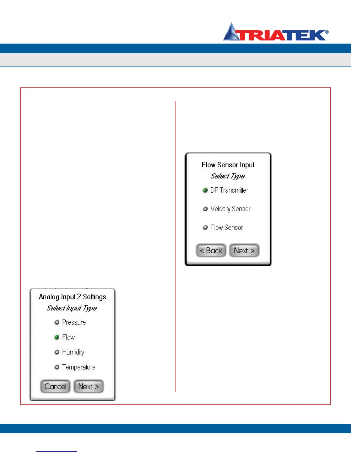
Setting up Analog Inputs for Flow
The FMS-1650 can be configured to calculate and display the real-time
Air Change Rate using one of three types of air flow input methods or
sensors. To configure one of the secondary analog inputs for air flow
measurement, select Flow from the Select Input Type configuration
screen as shown in Figure 38 and click the Next button. The Flow
Sensor Input configuration screen shown in Figure 39 appears,
allowing the user to select which type of sensor will be used for
measuring air flow.
After selecting the type of sensor that is being used to measure
air flow, clicking the Next button invokes two configuration screens
(Figure 40) which allow the user to specify the minimum and maximum
flows supported by the sensor. These values should be entered in
the engineering units which correspond to the type of sensor. For
example, the units would be either inches of water column (“WC) or
Pascals (Pa) for DP transmitters.
After specifying the maximum and minimum for the flow input, the
user is prompted to specify the cross-sectional duct area in square
inches as shown in Figure 43 if the type of flow sensor is either a
DP transmitter or a velocity transmitter. This duct area is required to
convert a differential pressure or a velocity to a real-time volumetric
flow, which may then used to calculate the air change rate (if enabled).
For round ducts, the cross-sectional area can be determined by
multiplying the square of the radius by pi (3.1416). As an example, the
cross-sectional area of a round 12” duct, which has a radius of 6”, is
calculated as follows:
Area
round duct
= π * r
2
= 3.1416 * (6”)
2
= 113.09 in
2
For rectangular ducts, the cross-sectional area can be determined by
multiplying the length and width. As an example, the cross-sectional
area of a duct that measures 24” by 12” is calculated as follows:
Area
rectangular duct
= L * W = 24” * 12” = 288 in
2
Figure 38. To calculate
& display air change
rate, input should be
configured for flow.
Figure 39. FMS-1650
supports three types
of sensors for Air Flow
measurement.