Thursday, May 14, 2009
Displays
LCD Design
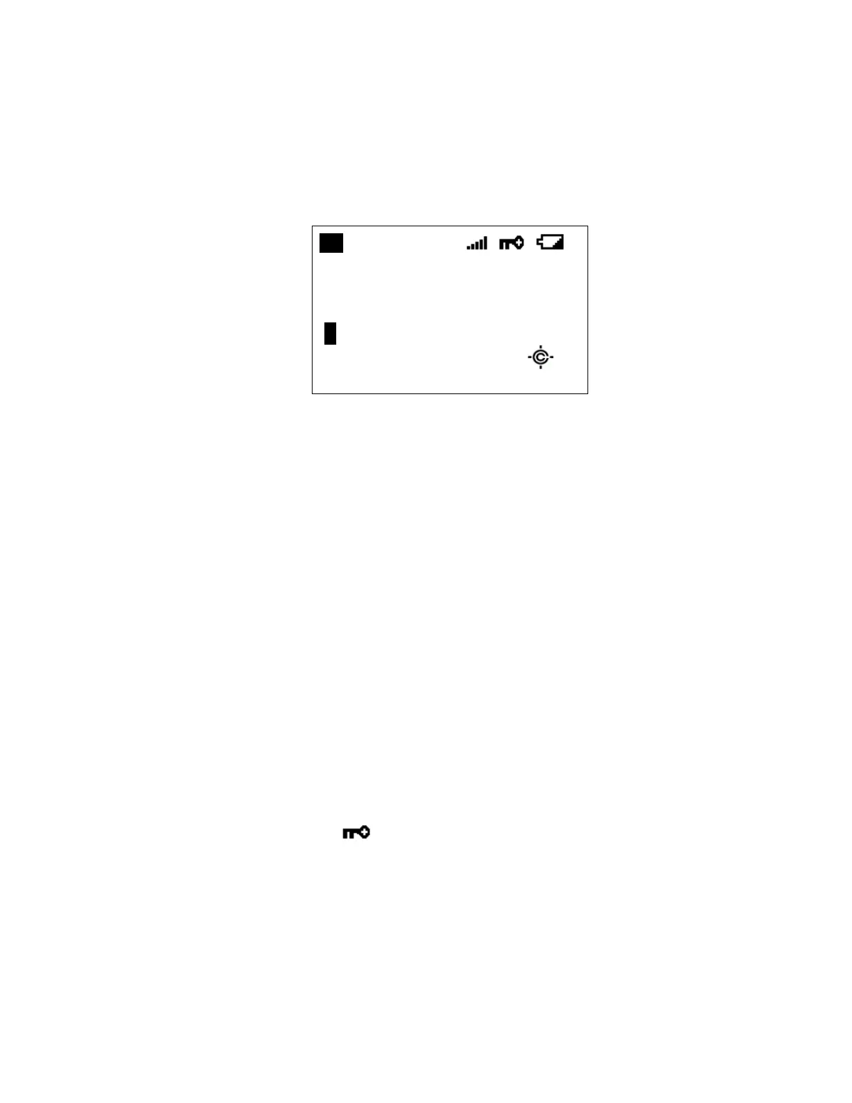
The reference design shown below is for illustration purposes only and is not intended to be a
photorealistic representation of the display.
ABCDEFGHI JKLMNOP
abcdefghi jklmnop
P WFM ATT P25
S0: 1 2 3 4 5 6 7 8 9 0
GRP 1 2 3 4 5 6 7 8 9 0 WX
Icons
Sx: : This icon appears with icons of System and Site Quick Key numbers (from “0” to
“99”). “x” shows the current ten’s place of Quick Keys for Systems or Sites.
GRP: This icon appears with icons of Quick Key number for Channel Groups (1 - 9, 0).
1 - 9, 0: In SCAN mode, the numbers of unlocked Quick Key for Systems/Channel Group
are displayed. The number for the currently scanned SQK set flashes.
In SCAN HOLD mode, the Quick Key number for the current System/Channel
Group appears.
Enabled User Range numbers appear in Custom Search; the current range’s
number blinks.
HOLD: This icon appears in Scan Hold, Search Hold and Close Call Hold Mode.
L/O: This icon appears at a locked out Channel or frequency.
PRI : This icon turns on during Priority Scan and this blinks during Priority Plus.
GPS: This icon appears when the scanner receives GPS data. This shows in the same
place as " ".
AM / FM / NFM / FMB
/ WFM: These icons show the modulation type.
ATT: This icon appears when a channel has attenuator on and blinks when global
attenuator is on.
P25: This icon shows the receiving digitalized voice of APCO P25.