EasyManua.ls Logo

Vermes MDS 358X - Pin Functions

Default Icon
183 pages
Print Icon
To Next Page IconTo Next Page
To Previous Page IconTo Previous Page
Loading...
Communication Interfaces
VTK-TR-BA-072e-1 - User Manual MDS 358X Series
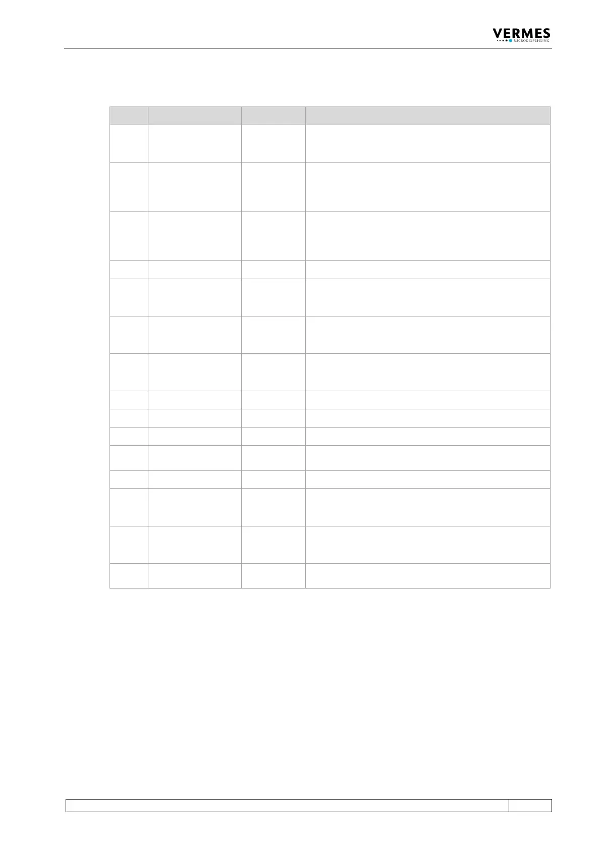
8.2.1 Pin Functions
PIN Characteristics Level Function
1
Output
0 / +24 V,
Ra=2.2 k
(valid for 0 V)
SingleDosOK
2
Input
0 / +24 V
Ri=1.3 k
Trigger Voltage Input
0 ... +5 V “Valve closed
+12 V ... +30 V “Valve opened“
Positive edge triggering
3
Input
0/ +5 V
Ri=400
Trigger Voltage Input
0 ... +0.8 V “Valve closed“
+3 V ... +5 VValve opened“
Positive edge triggering
4
Ground
___________
Ground
5
Output
0 / +24 V,
Ra=2.2 k
(valid for 0 V)
Set point Heating OK
6
Output
0 / +24 V,
Ra=2.2 k
(valid for 0 V)
Nozzle unit “adjusted” OK
(means green adjust LED)
7
Output
0 / +24 V,
Ra=2.2 k
(valid for 0 V)
Mains voltage OK
8
Reserved
___________
___________
9
Output
24 V/50 mA
Power supply to external trigger
10
Ground
___________
Ground
11
Input
0 / 20 mA,
Ri=500
Trigger Current Input
12
Reserved
___________
___________
13
Output
0 / +24 V,
Ra=2.2 k
(valid for 0 V)
For adjust: adjust failed. Adjust screw screwed in too
deep or not enough.
Outside adjust: general error (24 V = error)
14
Output
0 / +24 V,
Ra=2.2 k
(valid for 0 V)
DosOK Ready for dispensing (in the case of a pulse
package, at the end of the entire burst)
15
Input
___________
Trigger Abort; connection to ground, to interrupt
dispensing cycle; trigger blocked while active

Table of Contents