Initial Operation
VTK-TR-BA-072e-1 - User Manual MDS 358X Series
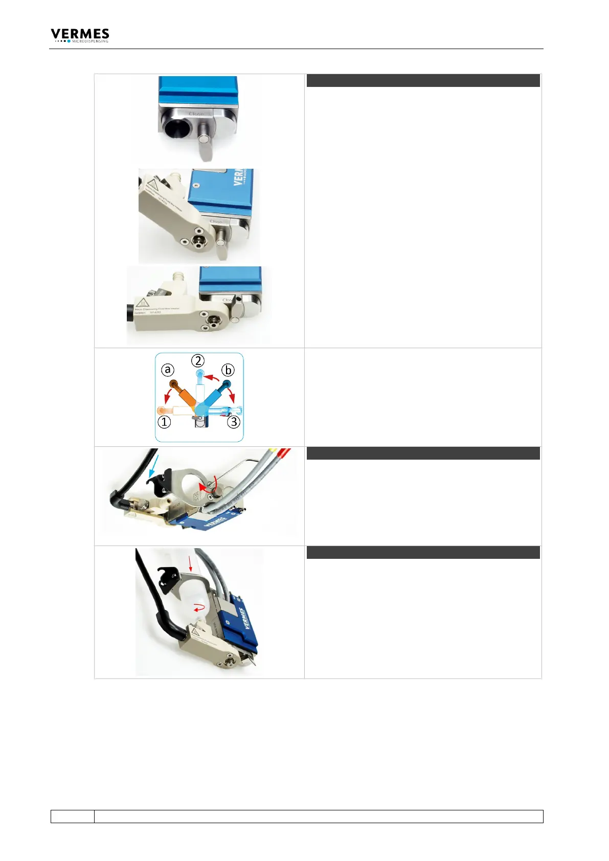
Turn the locking lever by 180° from “Close” to “Open”
position.
Push the fluid box carefully in a 45° angle onto the
valve.
Straighten the fluid box and close the locking lever.
Optional positions
The bayonet fluid box has three different locking
positions (1: 90°, 2: 0°, 3: +90°) in which the valve can
be operated. To fix in locking position 1, mount the
fluid box at position a. To fix in locking position 2 or 3,
mount the fluid box at position b.
Step 11 (cartridge holder)
Screw the cartridge holder on top of the valve body
(torque between 40 – 50 cN.m). Use the MDT 329 or a
hexagon socket key size 2. Depending on the size of
the cartridge, you have to select the correct cartridge
holder. Hook the heater connection of the fluid box
into the cartridge holder (see blue arrow).
Push the cartridge through the cartridge holder and
screw it clockwise into the thread of the cartridge
base.
Tab. 19: Assembling of the valve