Initial Operation
VTK-TR-BA-072e-1 - User Manual MDS 358X Series
6.3.3.2 Sensor Cable
This cable wrapped in yellow is provided to transfer data from the sensor integrated in the valve
to the control unit. Connect it as described below.
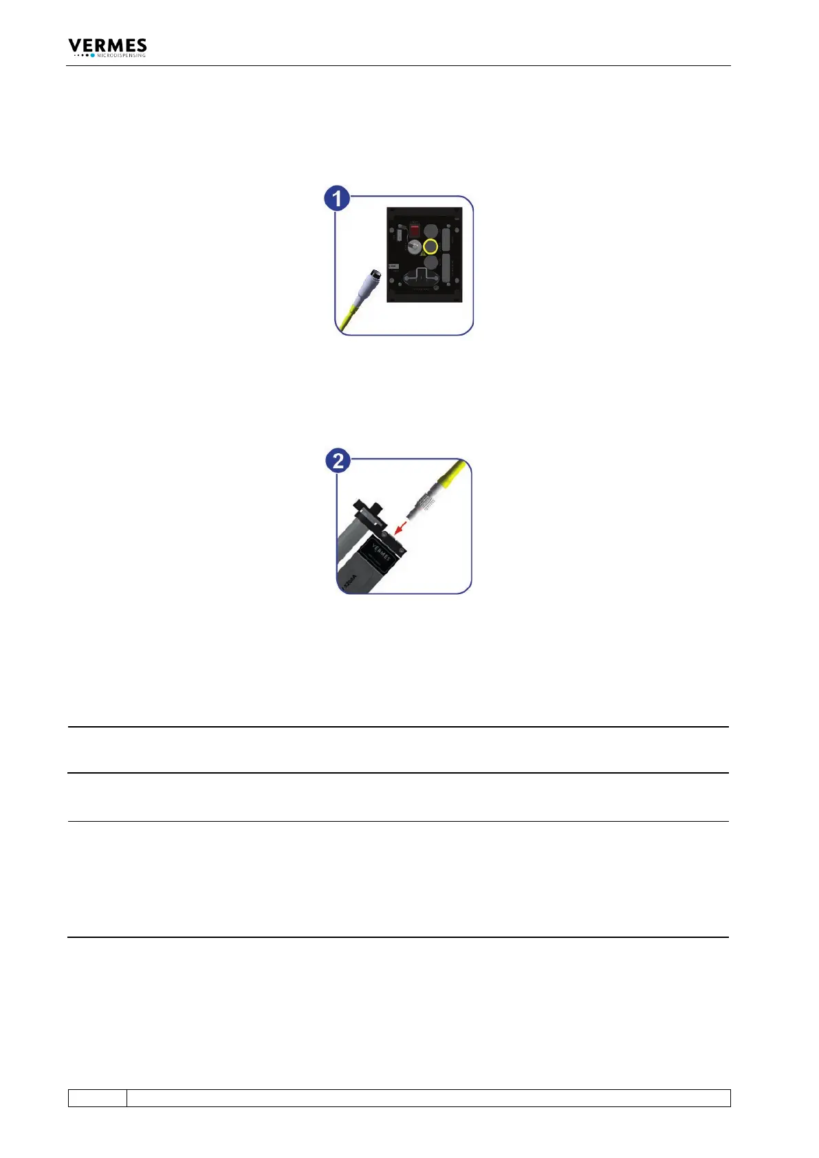
Fig. 25: Connecting the sensor cable – step 1
– Step 1: First, fix the sensor cable to the corresponding socket on the rear side of the control
unit.
Fig. 26: Connecting the sensor cable – step 2
– Step 2: The five-pin connector with a corrugated sleeve has to be connected to the yellow
marked, looped cable attached to the valve.
INFORMATION
Connecting cables
Verify during the connecting procedure that the red dots on the plugs point towards each other.
INFORMATION
Release latch for disconnection
To secure the connectors there is a latch, which you have to release before disconnection. You
have to grip the corrugated outhousing. Pull back the outhousing of the male connector to
release the latch (see Fig. 27, page 53). Then pull both connectors apart without losing the grip
and they will separate.
Do not pull at the cables!