Communication Interfaces
VTK-TR-BA-072e-1 - User Manual MDS 358X Series
8 Communication Interfaces
The control unit has three communication interfaces. There is a 9-pin serial interface, RS-232C, a
15-pin PLC interface and an AUX socket.
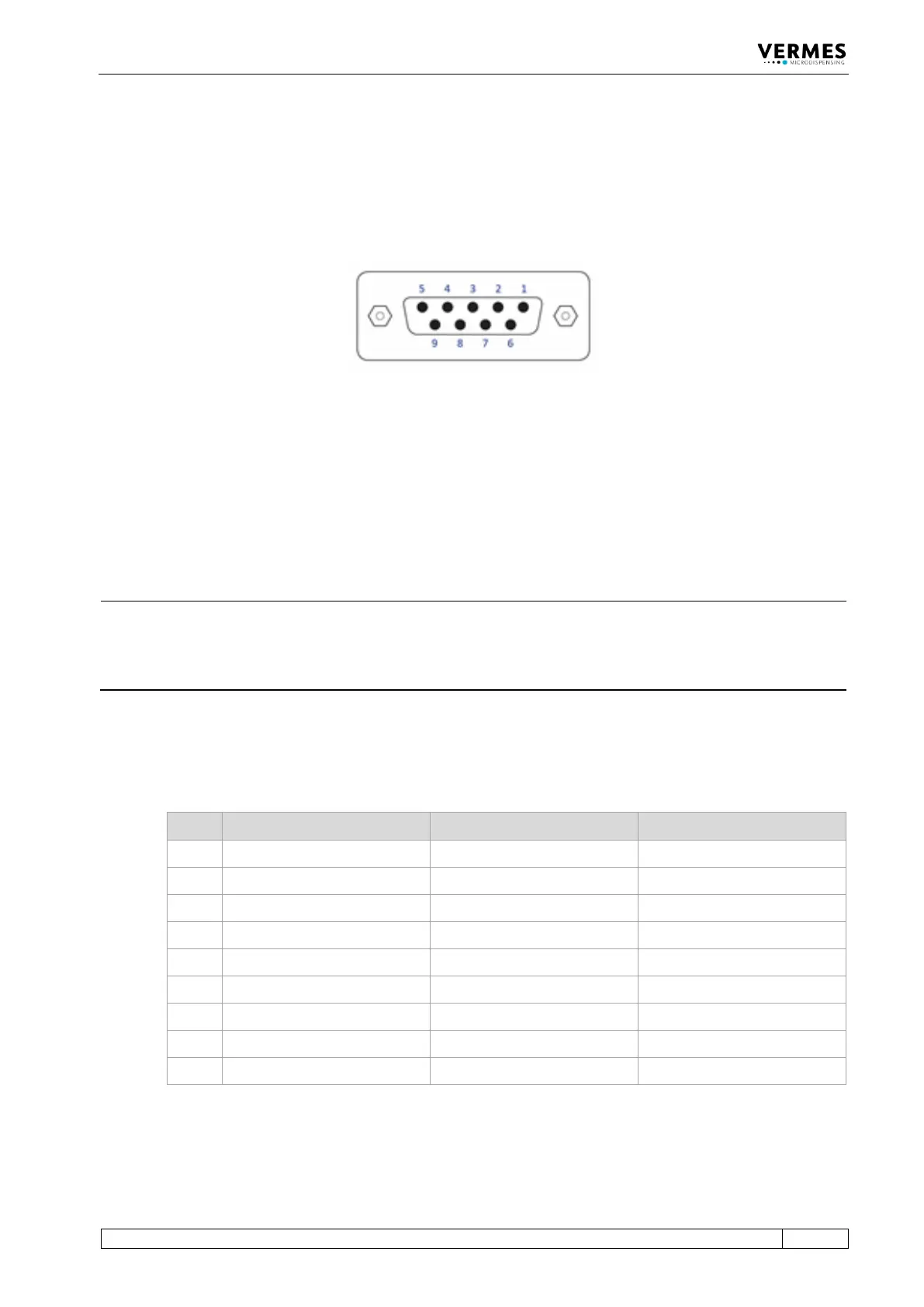
8.1 Serial Interface RS-232C: 9-Pin Sub-D
Fig. 61: Serial interface
The local interface is structured according to SCPI Standard.
These “Standard Commands for Programmable Instruments” represent a standardized set of
instructions used for control and programming, transmitted in form of ASCII text. They can be
generated by any selectable programming language in any environment. The serial interface
operates by means of software handshake. The hardware handshake communications are not in
use.
INFORMATION
Communication while triggering
Do not send instructions through this interface in the course of a running dispensing cycle.
Communication is only possible between distinct sequences (signal DosOK on “high”). This is
especially important during start-up of a heater.
After sending data or parameters to the control unit, you have to wait for the “OK” signal before
you can start further actions. You only can send data while the MDC is in the main menu.
8.1.1 Pin Functions
PIN Characteristics Level Function
1 Reserved ___________ ___________
Serial transmission signal
The RS-232C log of the control unit uses RS-232C standard and is designed for communication
via a serial cable, connected 1:1, with a Sub-D nine pin connector.