Operation
VTK-TR-BA-072e-1 - User Manual MDS 358X Series
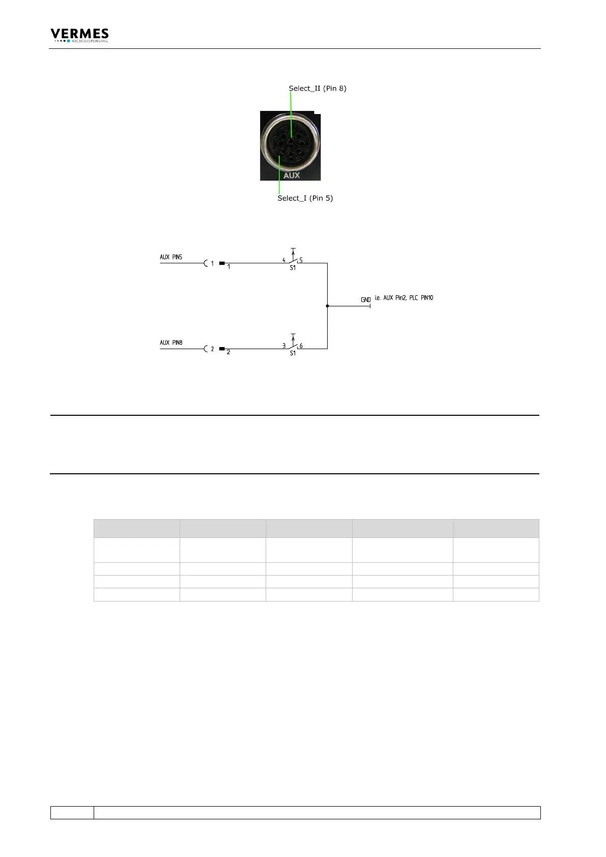
Fig. 53: Select Pins
Fig. 54: Schematic of usage of select pins
INFORMATION
Select pins with other commands
Select pins will be checked for triggering via PLC interface, for the serial commands
VALVE:AOPEN and SVALVE:AOPEN (in the versions without parameters) and when pressing the
key [trig].
You can also simulate the select pin settings for these two commands by using the command
extensions “S0”, “S1”, “S2” or “S3” (see paragraph 8.1.2.2 "Explanations", page 88).
Parameters Select1 Select2 Scenario „OFF“ Scenario „ON“
Setup 0 (working
configuration)
Tab. 23: Select Pin settings