Initial Operation
VTK-TR-BA-072e-1 - User Manual MDS 358X Series
Fig. 32: Connection Cable for FCV-AC/HF M12 to MDC
With the connection cable, you can connect the cooler connector of the FCV-AC 6.0 M12 to the
rear side of the control unit. Connect the air outlet of the flow control valve to the inlet of the
microdispensing valve (marked with “IN”). Use a suitable hose. Connect the air inlet of the flow
control valve to the compressed air supply.
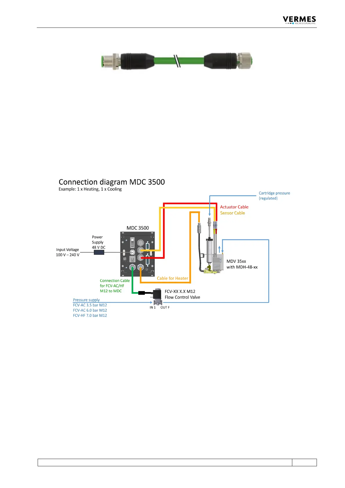
6.3.3.6 Connection Diagram
The picture below offers an overview of how to connection all parts with cables and hoses (using
one flow control valve and one heater as example).
Fig. 33: Connection diagram of MDS 358X