Operation
VTK-TR-BA-072e-1 - User Manual MDS 358X Series
7.8 Select Pins
Setups can be directly controlled via the select pins of the AUX socket (see Fig. 49), if “Scenario”
in the submenu “Scenario” is turned “OFF”. (In case “Scenario” is “ON” and you want to work with
the scenarios, please refer to paragraph 7.9.3, page 71.) The select pins allow you to switch in real
time between the setups 0 to 3.
INFORMATION
Setup 0 = working configuration
Please be aware that setup 0 is the working configuration and therefore is not programmed
additionally.
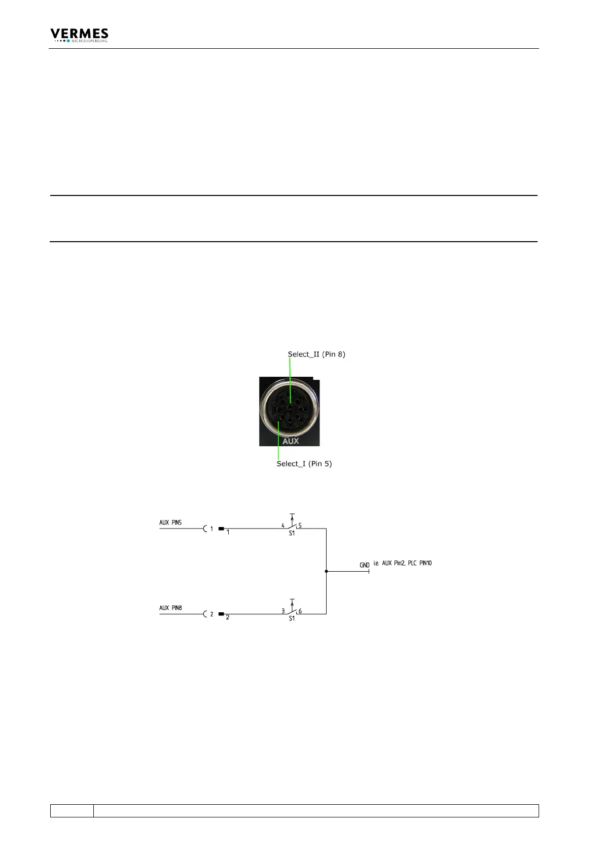
With the pins Select_I (AUX socket Pin 5) and Select_II (AUX socket Pin 8) it is possible to switch
rapidly between different sets of parameters. In their blank state, the select pins are on a high
level (pull-ups to 24 V). You have to switch them to low (Gnd) to select a different setup (see Fig.
51, page 69 and see Tab. 22, page 69). For additional information regarding the AUX socket, see
paragraph 8.3, page 119. You have to switch them before triggering.
Fig. 49: Select Pins
Fig. 50: Schematic of usage of select pins, example