Control Unit MDC
VTK-TR-BA-072e-1 - User Manual MDS 358X Series
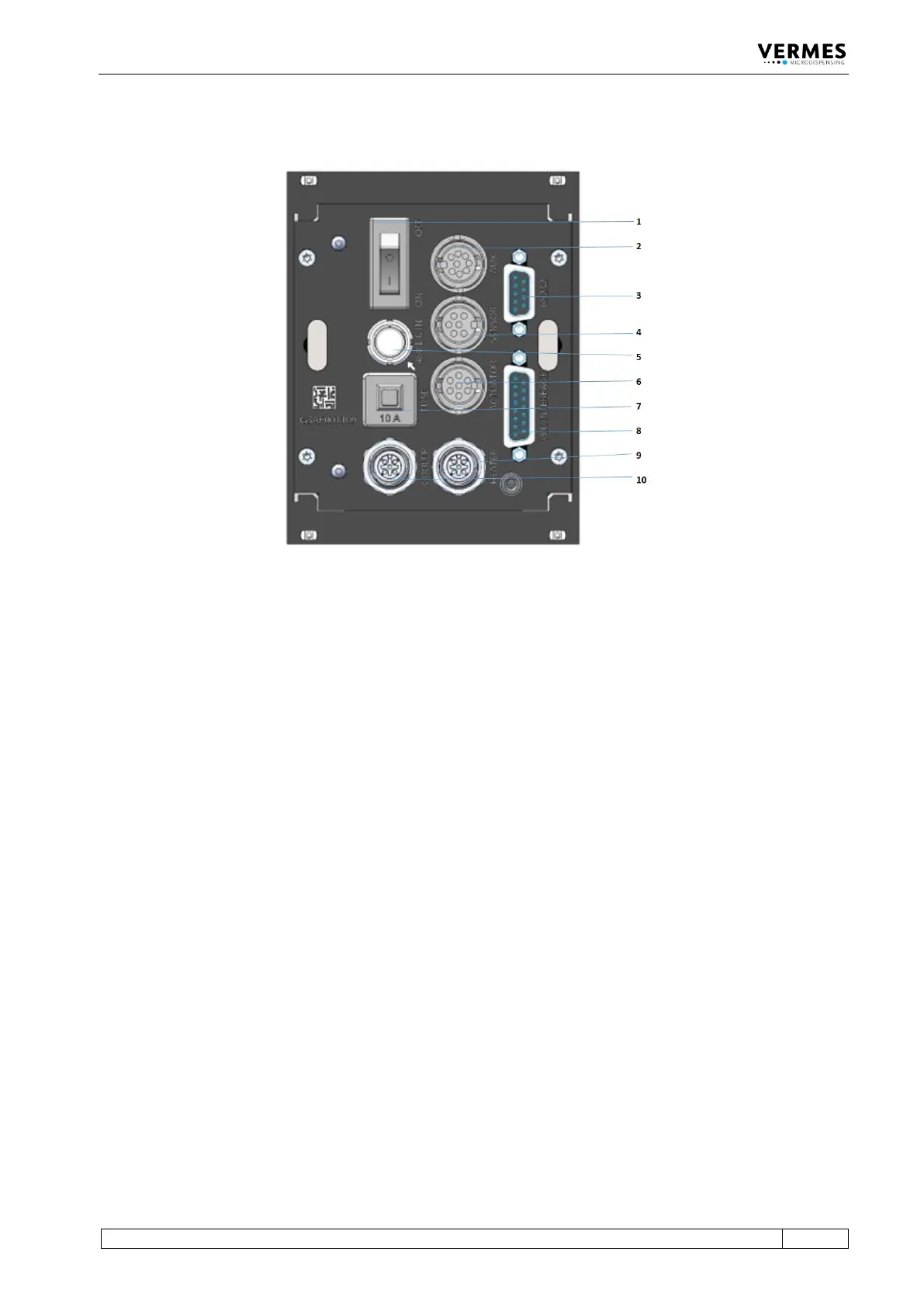
4.3 Back Side
Fig. 2: Back Side
1 ON/OFF switch
2 AUX socket
3 RS-232C interface (9-pin)
4 Sensor socket
5 Power connection
6 Actuator socket
7 10 A fuse
8 PLC interface (15-pin)
9 Socket for cooling
10 Socket for heating
ON/OFF switch:
By means of this switch, the unit is switched ON and OFF.
AUX socket:
This connector can be used for supply of an external device (e.g. an optocoupler) or to control
certain parameter setups or scenarios paragraph 8.3, page 119. It is one of the three interfaces of
the control unit (see Page 83 for the pin assignments).
RS-232C interface (9-pin):
Since the system offers the possibility of external programming of dispensing parameters via PC,
a local RS-232C is integrated to receive the data. For the communication protocol, refer to see
Fig. 3, page 24.
Sensor socket:
For the connection of the sensor cable.
Power connection:
Connects the control unit to power via an external power supply. The MDC needs 48 V DC. For
information regarding the pin functions, Page 113.