Initial Operation
VTK-TR-BA-072e-1 - User Manual MDS 358X Series
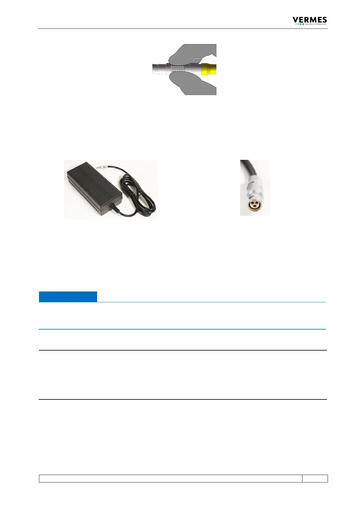
Fig. 27: Connector sensor cable - grip
6.3.3.3 Power Supply
Power to the control unit is supplied by the Switching Power Supply 48 V 4 A Push-Pull (order no.
1015251, see picture below).
Fig. 28: Switching Power Supply 48 V 4 A Push-Pull and its connector
– Step 1: Plug the Push-Pull connector into the socket at the bottom of the rear side of the
control unit. You can find the figure of the rear side in paragraph 4.3, page 23.
– Step 2: Connect the Switching Power Supply to the power supply.
– Step 3: Switch on the control unit by pressing the ON/OFF button on the rear side of the
control unit to the position “ON”.
IMPORTANT NOTE
Valve not connected
If a valve is not connected when switch on the MDC, an error message (“101 wrong valve“)
appears on the screen.
INFORMATION
MDC detects the heater and the cooler during start-up
During start-up, the MDC also checks if a heater and/or a flow control valve is connected. The
messages “Heater connected!” (or “Heater is disconnected!”) and “Cooler connected!” (or “Cooler
is disconnected!”) will be displayed. If the setting is selected, that a heater is automatically
activated during start-up, you need to confirm it by pressing the [enter]-key, when a heater is
connected.
6.3.3.4 Connecting a Heater
As an example. the heater MDH-48-BY (order no. 1014231, see Fig. 29, page 54) is shown to
demonstrate the connection of a heater.