FIG. 188
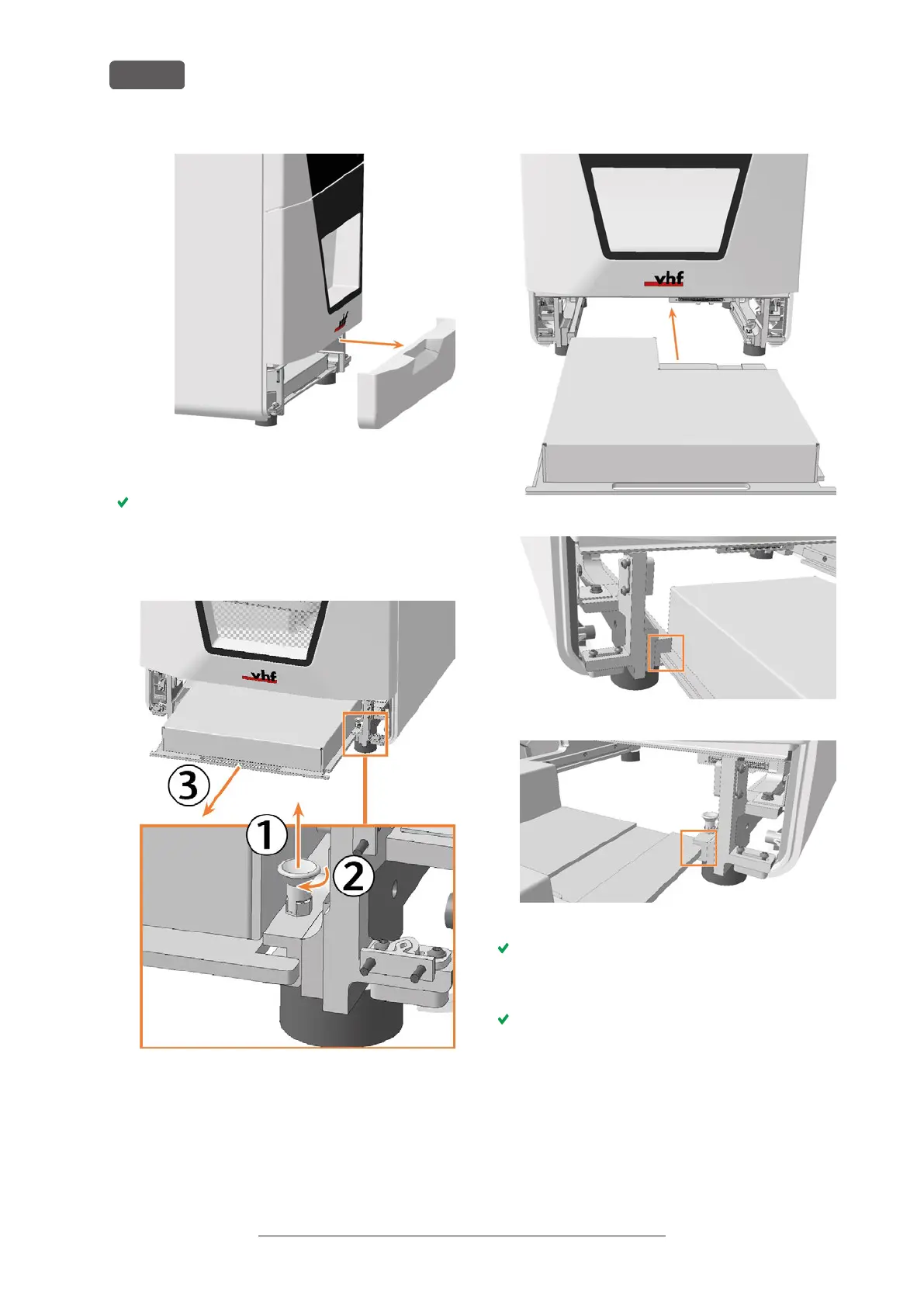
7. Pull the locking bolt upwards and turn it clockwise.
The locking bolt stays in position. The system
module shaft is unlocked.
8. Pull the system module forward out of the shaft by
the handle.
FIG. 189
9. Slide the spare system module with the connector
on the right rear side into the system module shaft.
Insert the base plate of the system module into the
left and right guide rails.
FIG. 190
FIG. 191
FIG. 192
You can feel the connector sliding into the system
module slot.
10. Turn the locking bolt counterclockwise.
The locking bolt slides down. The system module
shaft is locked.
Original Operating Instructions:E5
Version: 4/27/2023
Maintenance
EN 74