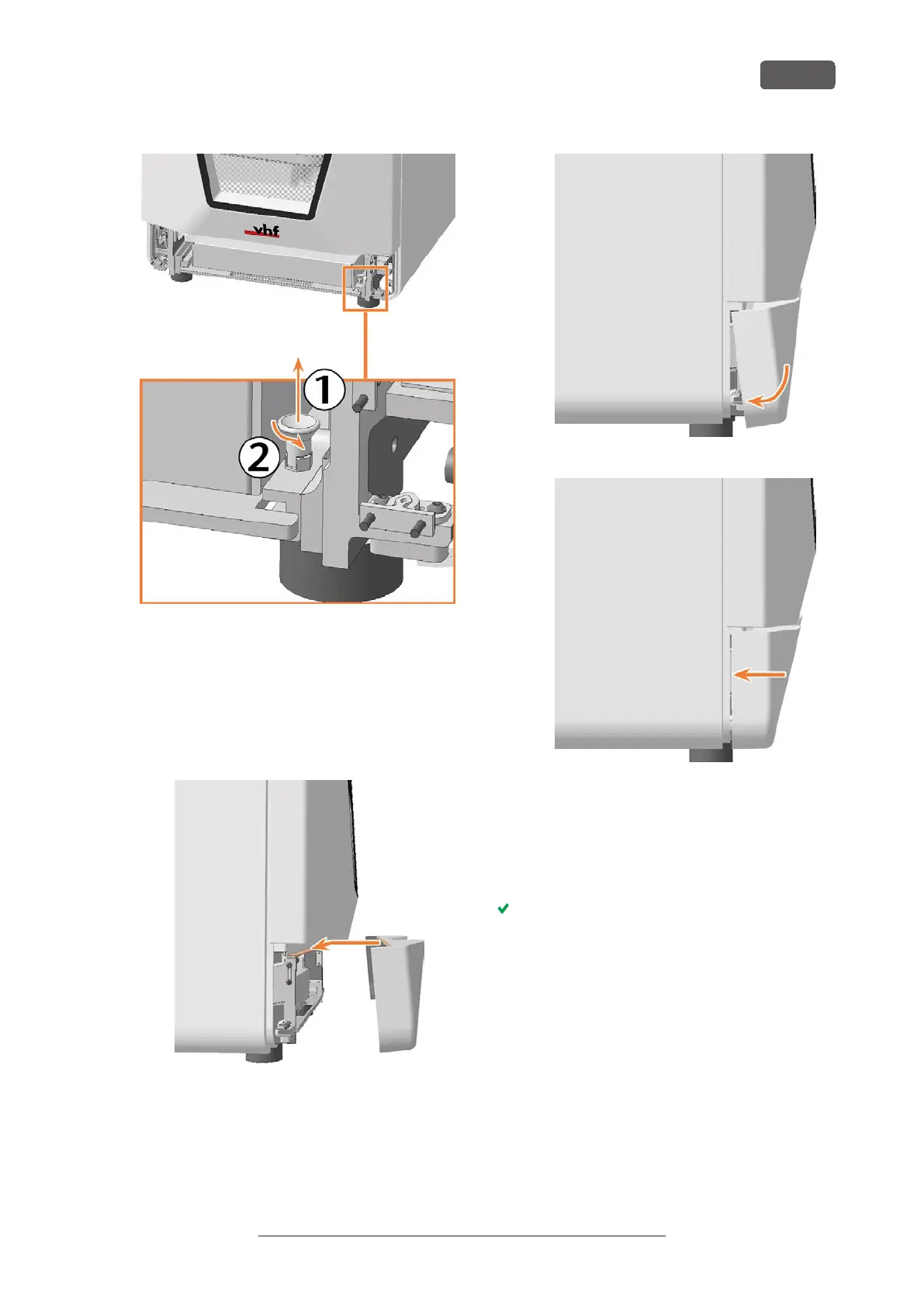
FIG. 193
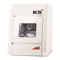
11. Install the lower service cover:
a. Place the top edge of the cover on the posi-
tioning bar above the system module shaft.
b. Tilt the bottom half of the cover to the
machine.
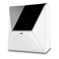
c. Press the cover until it snaps into place.
FIG. 194
FIG. 195
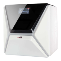
FIG. 196
12. Connect the Ethernet and power cables.
13. Switch on the machine at the main power switch.
14. Start DENTALCNC
15. Contact customer service.
Customer Service sets up the system module.
Maintenance
EN 75
Original Operating Instructions: E5
Version: 4/27/2023