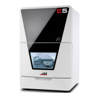
8. Remove the blank from the blank holder if present.
Mounting & removing blanks – on page27
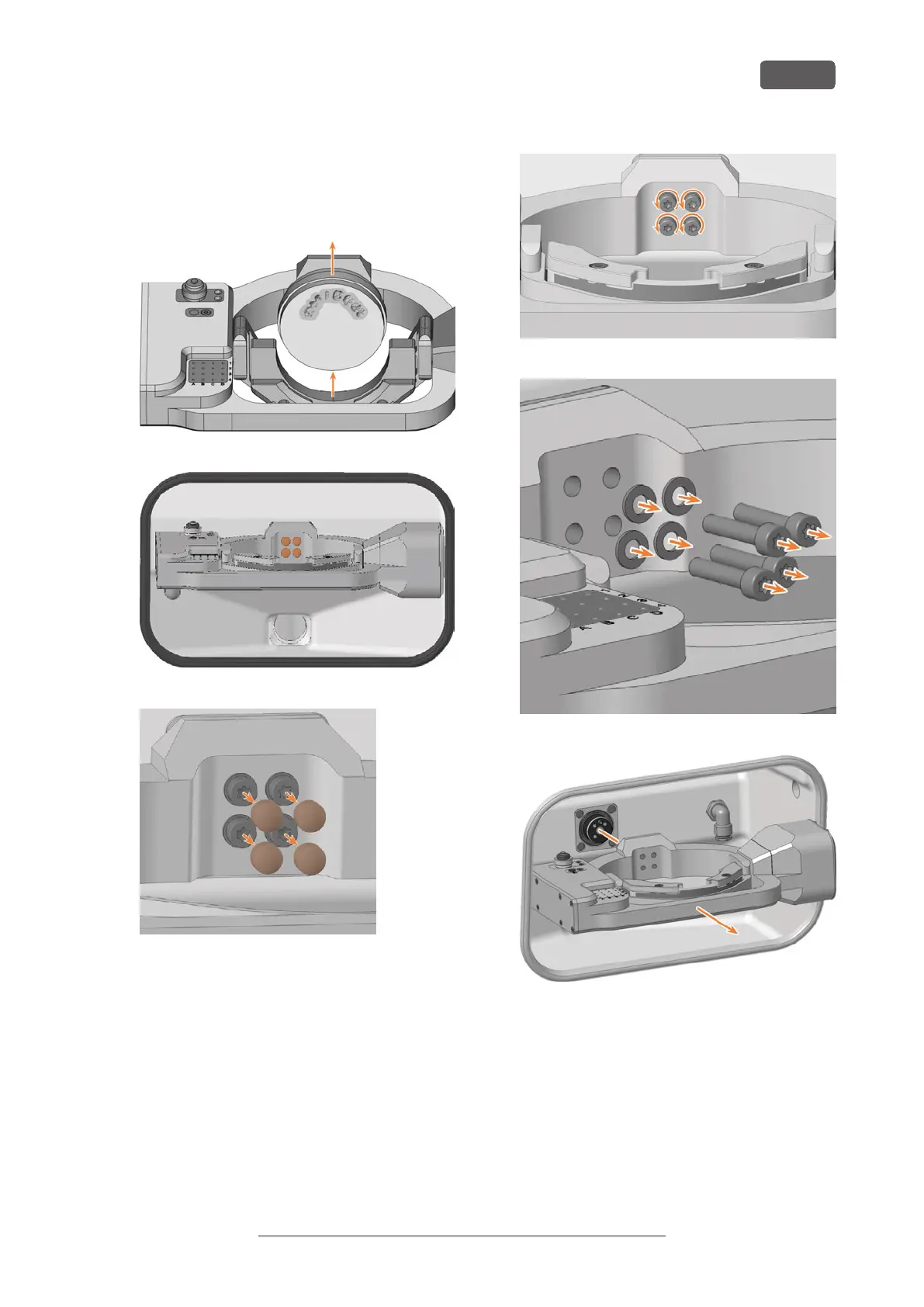
9. Pull the 4 cover caps (marked orange) off the 4
fixing screws on the A-B axis module.
FIG. 265
FIG. 266
FIG. 267
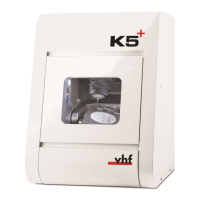
10. Unscrew the 4 fixing screws of the A-B axis module
with the angle screwdriver. Remove the fixing
screws and washers.
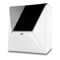
11. Grasp the A-B axis module with both hands and
pull it forwards off the driveshaft. Remove the A-B
axis module from the working chamber.
FIG. 268
FIG. 269
FIG. 270
12. Using both hands, slide the spare A-B axis module
onto the driveshaft. Insert the positioning pin on
the driveshaft (marked orange) into the opening at
the rear of the A-B axis module (marked green).
Maintenance
EN 91
Original Operating Instructions: E5
Version: 4/27/2023