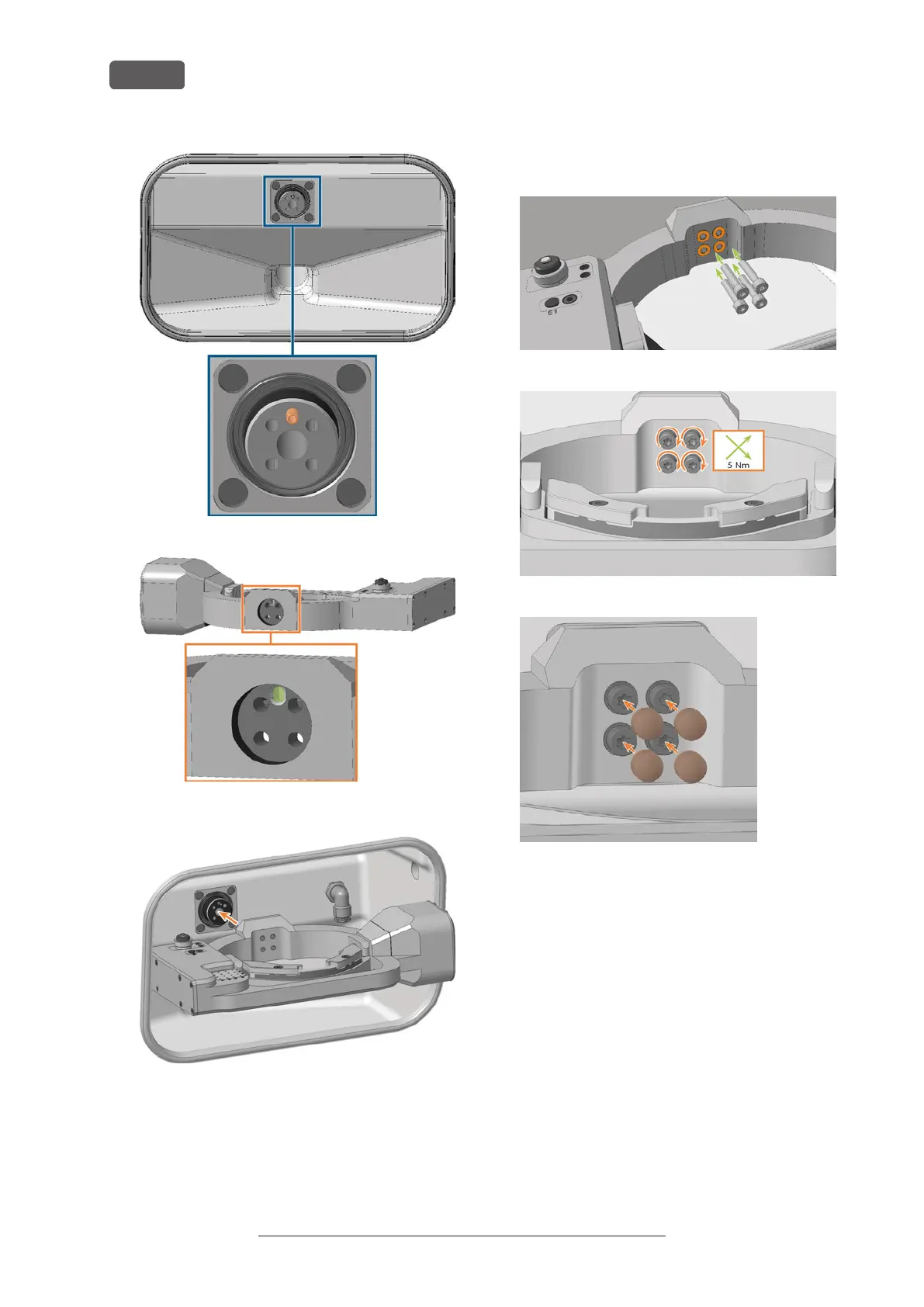
FIG. 271 POSITIONING PIN ON THE (MARKED ORANGE) DRIVESHAFT
FIG. 272 POSITIONING PIN DRILLING AT THE REAR OF THE A-B AXIS
MODULE (MARKED GREEN)
FIG. 273
13. Use the torque screwdriver (5.0Nm with TX25 bit)
and tighten the A-B axis module crosswise with the
4 washers (marked orange) and the 4 fixing screws.
14. Attach the 4 cover caps to the 4 fixing screws of the
A-B axis module.
FIG. 274
FIG. 275
FIG. 276
15. Connect the A-B axis module power cable to the
connection on the lower left side of the A-B axis
module:
a. Plug in the cable.
b. Close the screw cap.
Original Operating Instructions:E5
Version: 4/27/2023
Maintenance
EN 92