112
Maintenance
Sensors
The sensors react when a magnet falls within the preset sensor di-
stance. Therefore the magnet must be adjusted to a specific distance
in relation to the sensor.
The distance (A) of all of the sensors must be adjusted to 3 - 5 mm.
Procedure:
> Loosen both screws.
> Adjust the sensor until the required distance A = 3 - 5 mm is obtai-
ned.
> Ti ght en both screws.
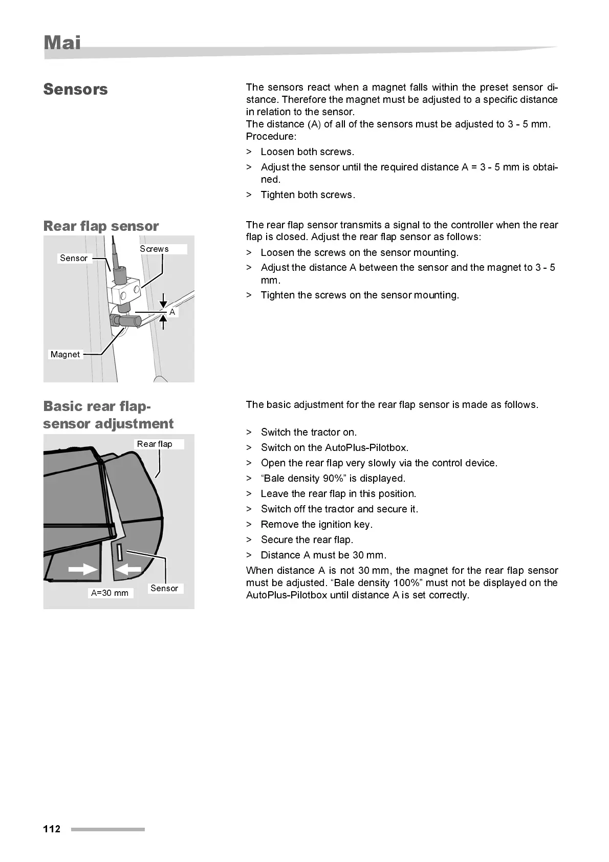
Rear fla p se nsor
The rear flap sensor transmits a signal to the controller when the rear
fl ap i s closed. Adjust the rear flap sensor as follow s:
> Loosen the screws on the sensor mounting.
> Adjust the distance A between the sensor and the magnet to 3 - 5
mm.
> Ti ght en the screws on the sensor mounti ng.
Basi c rea r flap -
sensor adjustment
The basic adjustment for the rear fl ap sensor is made as foll ow s.
> Switch the tractor on.
> Switch on the AutoPlus-Pilotbox.
> Open the rear flap very slowly via the control device.
> “Bal e density 90%” i s displ ay ed.
> Leave the rear flap i n thi s position.
> Switch off the tractor and secure it.
> Remove the ignition key.
> Secure the rear flap.
> Di stance A must be 30 mm.
When distance A is not 30 mm, the magnet for the rear flap sensor
must be adjusted. “Bal e density 100%” must not be displ ayed on the
AutoPlus-Pilotbox until distance A is set correctly.
A
Screws
Sensor
Magnet
A=30 mm
Sensor
Rear flap