Rev AB Terminals 9-13
Videojet 8520 Operator Manual
Technical Data - Shaft Encoder
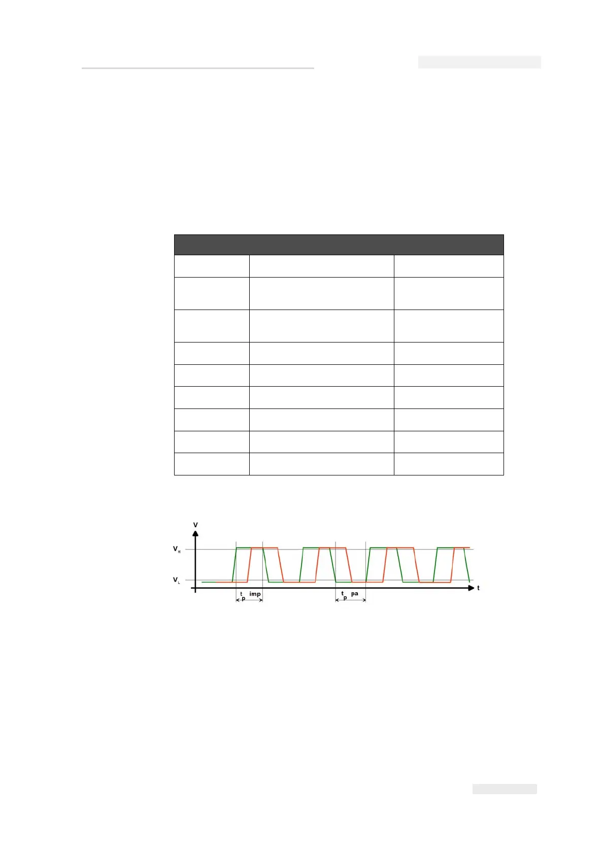
The output signal of the shaft encoder must be a rectangular pulse signal.
This signal input on the Videojet 8520 is equipped with a pull-up resistor
against +5 V. It is sufficient if the primary detector can only drive the
output signal actively to ground (0 V = Low level) (open collector output).
If the primary detector used can also be actively run on a high level (+5 V),
the output voltage must not exceed +5.5 V.
Table 9-7 lists the specifications for the shaft encoder connection.
A shaft encoder from another manufacturer can be used instead of the
standard type from Videojet at any time. However, any such shaft encoder
must have exactly the same values as those set out in “Terminals” on
page 9-11.
Following are the important information about the use of a shaft encoder:
Properties of the shaft encoder output signal (pulse)
V
max
Maximum output voltage 5.5 V
V
L
Low level output voltage
pulse
0 to 0.8 V
V
H
High level output voltage
pulse
2.0 to 5.5 V
I
out
Output current 5 mA (min.)
t
p imp
Signal length of pulse 200 ns (min.)
t
p pa
Signal length of pause 200 ns (min.)
R
imp-pa
Ratio of pulse to pause 10% to 90%
R
imp/m
Ratio of pulse/meter 5000 to 15000 Imp/m
f
max
Maximum pulse frequency 300 kHz
Table 9-7: Specifications of the Shaft Encoder
Figure 9-12: Output Signal Profile of Shaft Encoder