3-18 Installation of Printhead and Ink Cartridge Rev AB
Videojet 8520 Operator Manual
7 Make sure that you account for the product path direction when
fitting the head plate to the bottom of the printhead. The cutout on the
underside of the head plate points in the direction of movement of the
belt.
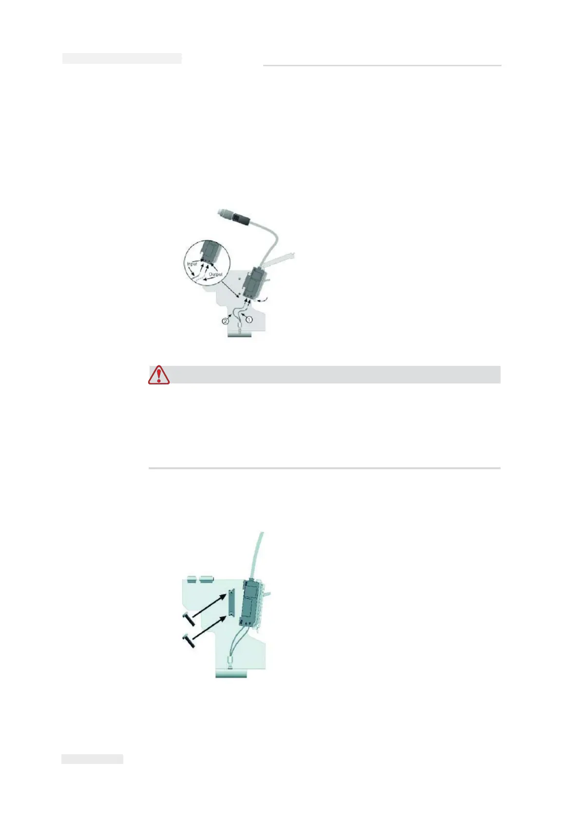
8 Insert the optical fibre in the photoelectric cell and fasten it with the
quick-release fastener.
EQUIPMENT DAMAGE. When connecting the optical fibre, make
sure the output
T 1 (insulation of optical fibre is identified with
dots) and the input
S 2 (insulation of optical fibre is not identified)
is not substituted. Otherwise the sensor will not be able to issue the
correct signal.
9 Fasten the installation mount to the printhead with the supplied
screws and latch the photoelectric cell onto the installation mount.
10 Insert the connector of the photocell cable into the socket on the
printhead provided to this effect, and tighten the connector by hand.