Rev AB Installation of the Parallelogram (Optional) 3-29
Videojet 8520 Operator Manual
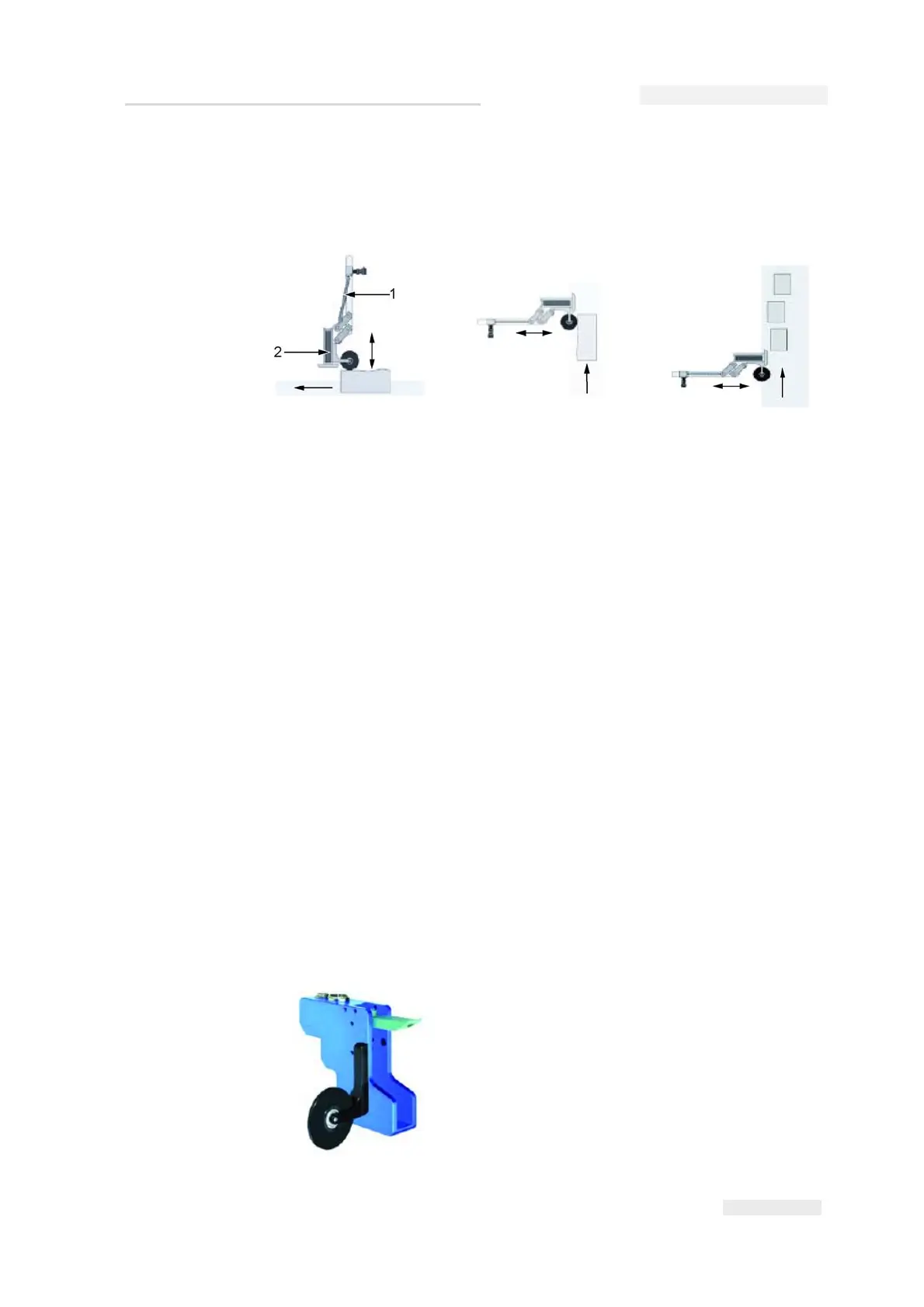
It is suitable for side or top mounting. The maximum deflection is 90 mm,
measured from the rest position. Figure 3-46 shows the possible positions
of the parallelogram.
Description of functions
The springs included in delivery have different tensile strengths. The
different attachment positions are for weight compensation for one, two,
three, and four head systems and for adjusting the spring force in the case
of vertical printing.
The locating wheel or the deflector moves the parallelogram to the correct
position and thereby facilitates initial distance compensation which
reduces impact on the material.
The choice between the deflector and locating wheel depends on the
specific application.
How to Install the Locating Wheel with the New Sensor
If a locating wheel is used, do the following tasks to install the new sensor
on the printhead:
The locating wheel is screwed on as before with two size M3 screws (6mm
long).
Figure 3-46: Parallelogram Positions
At the top
Lateral, uneven/cambered
products or packages
Lateral, different
product positions
1. Parallelogram
2. Printhead