68 MRIdian® system L-0009 Release 4.5 ViewRay, Inc.
Chapter 3: System Coordinates
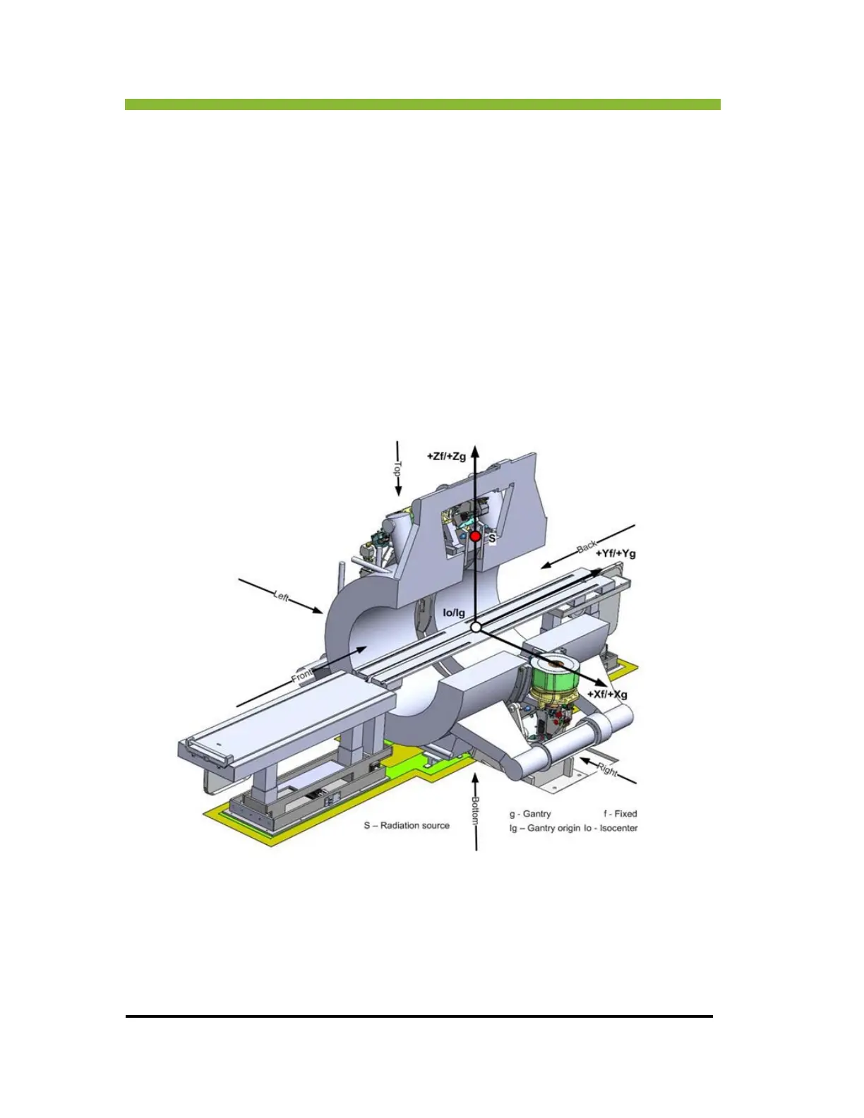
In accordance with IEC 61217, the MRIdian® system has a fixed right-handed coordinate
system with the coordinate system origin at the isocenter of the machine.
The “+Z” axis is aligned towards the top of the machine and the “-Z' axis towards the bottom
of the machine. The
“+Y” axis is aligned toward the back of the machine and “-Y” axis is
aligned towards the front of the machine. The “+X” axis is aligned towards the right of the
machine and the “-X” axis is aligned towards the left of the machine.
The radiation source location for the “0°” position is indicated by the red dot with label “S,”
tha
t is the radiation source is aligned on the “+Z” axis. The isocenter is illustrated by the white
dot with label “Io.”
3.1.2 Gantry Coordinate System
The gantry at its “0°” position.
The gantry system is coincident with the fixed system and “Io” and “Ig” are at the same loca-
tion. The fixed system is the mother system for the gantry system. The gantry coordinate sys-
tem rotates with the gantry and can only rotate about the Y axis.
 Loading...