ViewRay Inc. MRIdian® system L-0009 Release 4.5 69
Chapter 3: System Coordinates
In this system the “+Z” axis is aligned towards the top of the machine and the “-Z” axis
towards the bottom of the machine. The “+Y” axis is aligned toward the back of the machine
and “-Y” axis is aligned towards the front of the machine. The “+X” axis is aligned towards the
right of the machine and the “-X” axis is aligned towards the left of the machine.
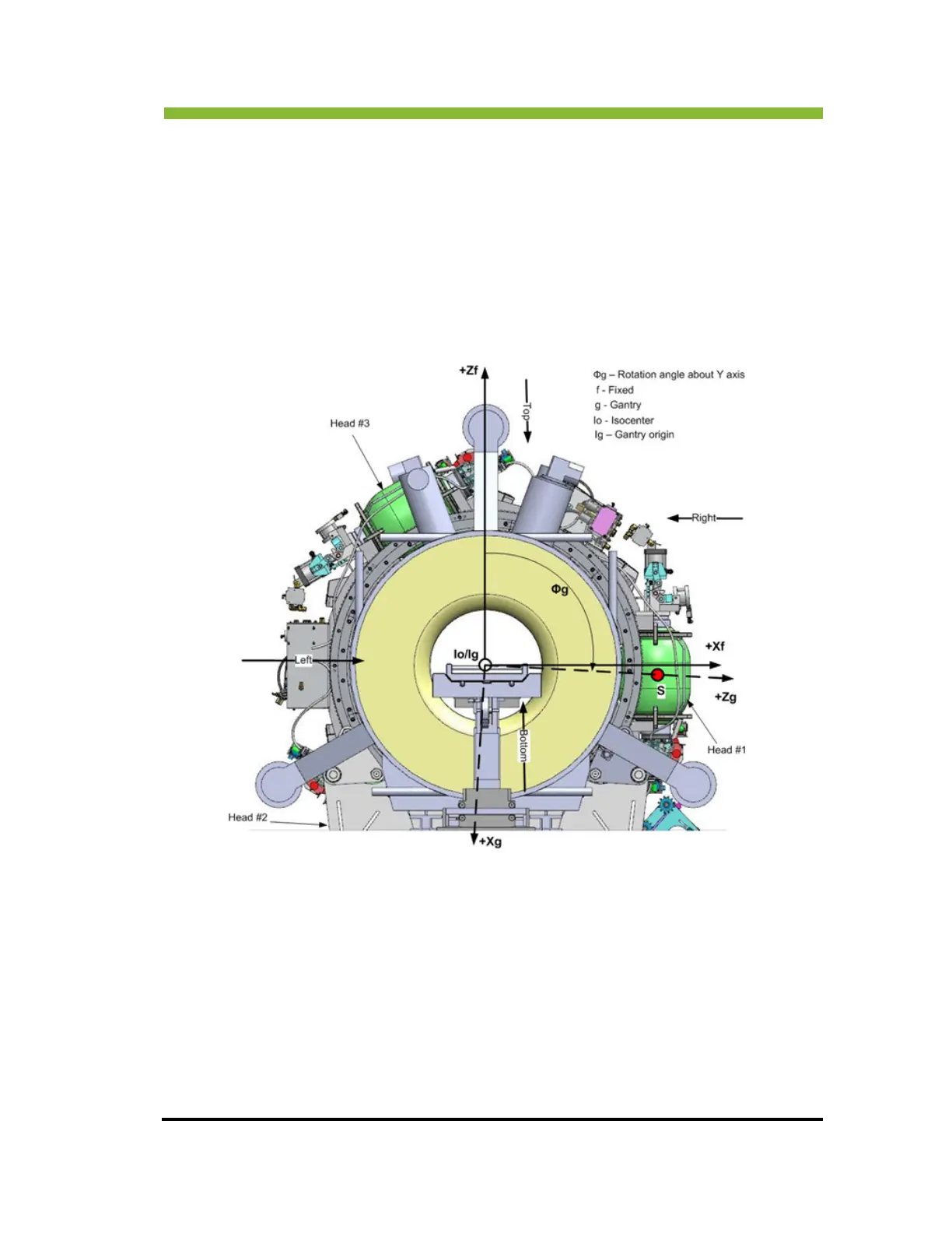
3.1.3 Gantry Rotation
Positive (Clockwise) gantry rotation is illustrated below. The view is from the front of the
gantry and the angle is slightly greater than 90
.
3.1.4 Beam Limiting Coordinate System
There are three beam-limiting devices (multi-leaf collimators), each located 120 degrees
apart from the other. The beam limiting coordinate system is the same as that of the gantry.
The beam limiting devices rotate with the gantry. When one beam limiting device is at the
“0°” position, its coordinate system is defined with the same axis orientation as the gantry
system. The source “S” and origin “Ib” are at the same position.
The “+Z” axis is aligned to the top of the machine and the “-Z” axis to the bottom of the
machi
ne.
 Loading...