ViewRay Inc. MRIdian® system L-0009 Release 4.5 73
Chapter 3: System Coordinates
3.1.8 Planning and Visualization using Coordinate System
The visualization system displays the Multi-planar reconstruction (MPR) planes as depicted in
the three following diagrams.
In each diagram the image is shown in a black square. The orientation on the user interface
(UI) scr
een is the same orientation as the square in the top left corner of each diagram.
The axial, lateral and vertical images are always displayed in the fixed coordinate system. Not
e
that for all three orientations, the patient is shown head first, supine, going into the gantry
from the front.
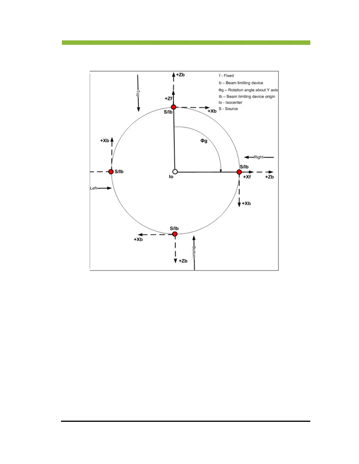
In this system the “+Z” axis is aligned to the top of the machine and the “-Z” axis to the
bot
tom of the machine. The “+/-Y” axis is not visible. The “+X” axis is aligned to the right of
the machine and the “-X” axis is aligned to the left of the machine.