4.
Make sure that the movable part of the assembly is parallel to the fixed part of
the assembly at both positions. Adjust with screws [B] and [C].
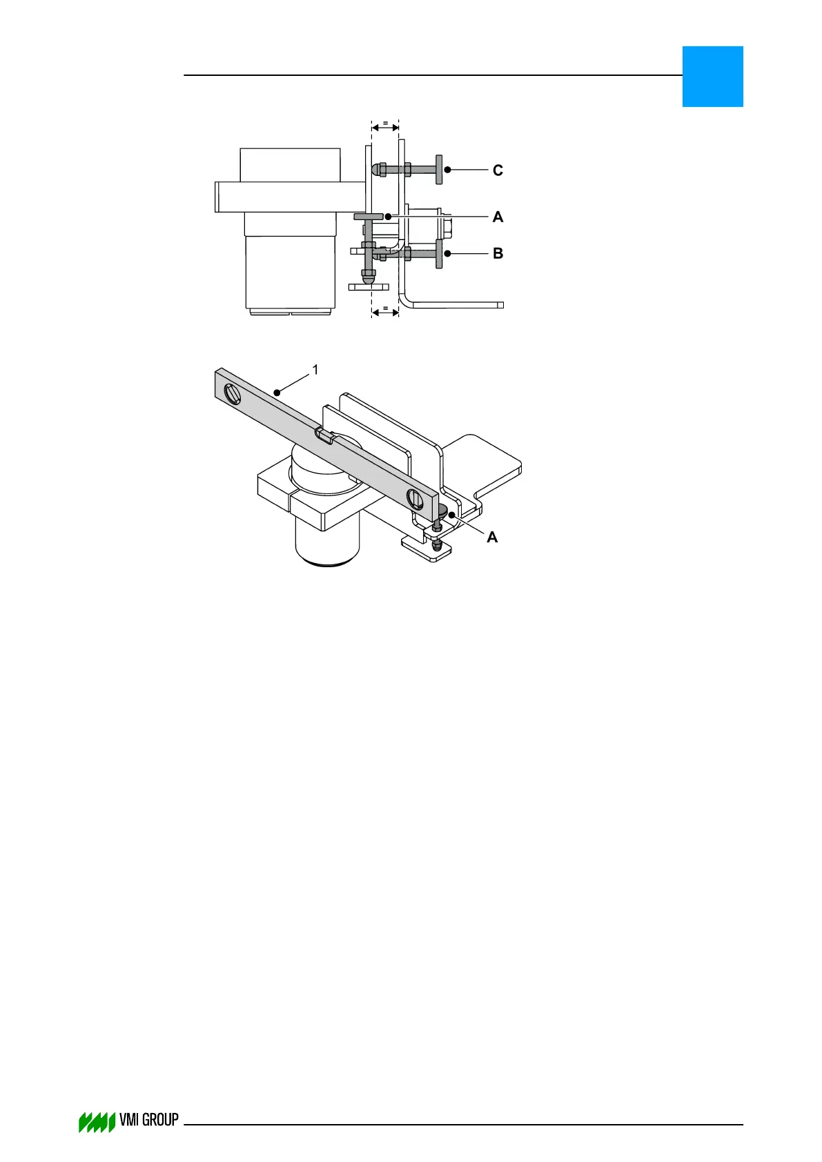
5.
Make sure that the camera is perpendicular to the light source using adjustment
screw [A].
Use a spirit level. [1]
6. The camera image in the VVSUDISPLAY SENSOR tab should be acceptable, if not,
adjust with adjustment screw [C].
ALIGNMENTS, ADJUSTMENTS AND CALIBRATIONS
VVS Breaker
5
THINKING FORWARD
VMI Vision System VVS (OL82) VVSX 13.0.12.0, VVSU 3.0.6 / 4 / 2016-07-11 / pd#175592
5-6