6.2 Parameter buffer
A schematic representation of the reserved space (in words of 16 bits):
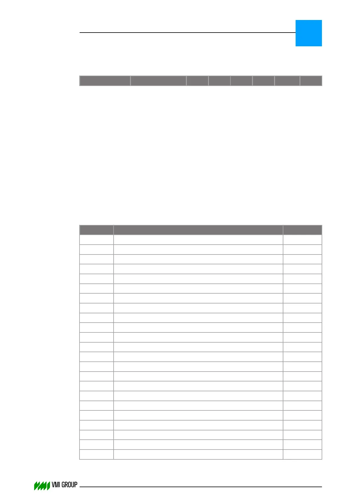
Communication Space for: BR1 BR2 BR3 BR4 PA/BP TR
PLC ® VVS Parameter buffer 30 30 30 30 50 15
PLC ® VVS Command buffer 1 1 1 1 1 1
PLC ® VVS Status buffer 32 32 32 32 10 10
PLC ® VVS Extended Status
(Tread Error)
buffer
x x x x x 350
Parameter buffers contain material, correction and offset specifications. Parameters are
sent to VVS during system start‑up, size change etc. These VVS parameters can be a
combination of HMI parameters.
Refer to the HMI Operation section of the Technical Manual of your machine for information
on how to edit the HMI parameters. Also, a description of the individual HMI parameter is
found in the Technical Manual of your machine.
6.2.1 Material parameters for Breaker
The length of each Breaker parameter buffer is 30 words.
Word Parameter Dimension
0 Offset Leading Edge 0.1 mm
1 Offset Breaker 0.1 mm
2 Offset Trailing Edge 0.1 mm
3 Tip correction Leading Edge Breaker 0.1 mm
4 Tip correction Trailing Edge Breaker 0.1 mm
5 Length for tip correction Breaker 0.1 mm
6 Breaker angle 0.1 mm
7 Breaker thickness 0.1 mm
8 Breaker width 0.1 mm
9 Breaker split width 0.1 mm
10 Breaker outer tolerance 0.1 mm
11 Breaker inner tolerance 0.1 mm
12 Calibration length 0.1 mm
13 Breaker length 1 mm
14 Algorithm selection 1 %
15 Splice correction 1/9 0.1 mm
16 Splice correction 2/9 0.1 mm
17 Splice correction 3/9 0.1 mm
18 Splice correction 4/9 0.1 mm
19 Splice correction 5/9 0.1 mm
20 Splice correction 6/9 0.1 mm
21 Splice correction 7/9 0.1 mm
22 Splice correction 8/9 0.1 mm
PARAMETERS
Parameter buffer
6
THINKING FORWARD
VMI Vision System VVS (OL82) VVSX 13.0.12.0, VVSU 3.0.6 / 4 / 2016-07-11 / pd#175592
6-4