5.4 VVS Tread
5.4.1 Align the camera
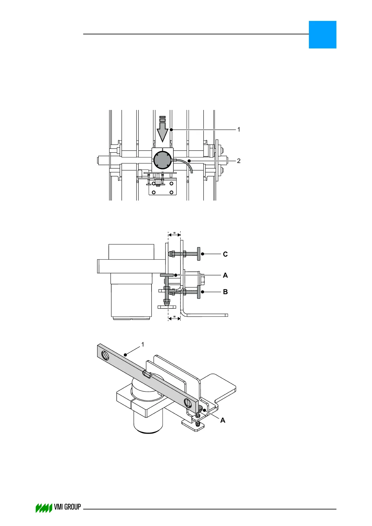
1. Check if the light source is working and make sure it is clean!
Alignment of the light source is not necessary.
2. Check the alignment of the camera.
Use the camera connector [2] as a reference relative to the material direction [1].
The camera connector must be on the left when you look in the direction of the
material.
3.
Make sure that the movable part of the assembly is parallel to the fixed part of
the assembly at both positions. Adjust with screws [B] and [C].
4.
Make sure that the camera is perpendicular to the light source using adjustment
screw [A].
Use a spirit level. [1]
5. The camera image in the VVSUDISPLAY SENSOR tab should be acceptable, if not,
adjust with adjustment screw [C].
ALIGNMENTS, ADJUSTMENTS AND CALIBRATIONS
VVS Tread
5
THINKING FORWARD
VMI Vision System VVS (OL82) VVSX 13.0.12.0, VVSU 3.0.6 / 4 / 2016-07-11 / pd#175592
5-25