2-30 DHS Installation
5. Remove one of the module-securing screws only so the existing board stays in place,
and retain the screw for later use.
6. Insert one of the stand-off posts into the screw position where the screw from Step 5
was removed.
7. Tighten securely by hand, then snug tight using a small hand tool. It is very important
not to over-tighten any screw or stand-off post as damage to the board may occur.
8. Repeat Steps 5 through 7, until all module screws are replaced with stand-off posts.
9. Position the new 3 x 8 module over the stand-off posts installed and use the screws
removed in the previous steps to secure it in place on the stand-off posts.
10. Once mounted, carefully insert the bus ribbon cable into the next available bus
connector on the CPU board.
11. Connect the amphenol-ended cable to the connector on the 3 x 8 module.
12. Secure cable in place with a clamp or cable tie.
13. Replace KSU cover and secure with cover screws, and restore KSU power when all
wiring is complete. Or continue with the installation process.
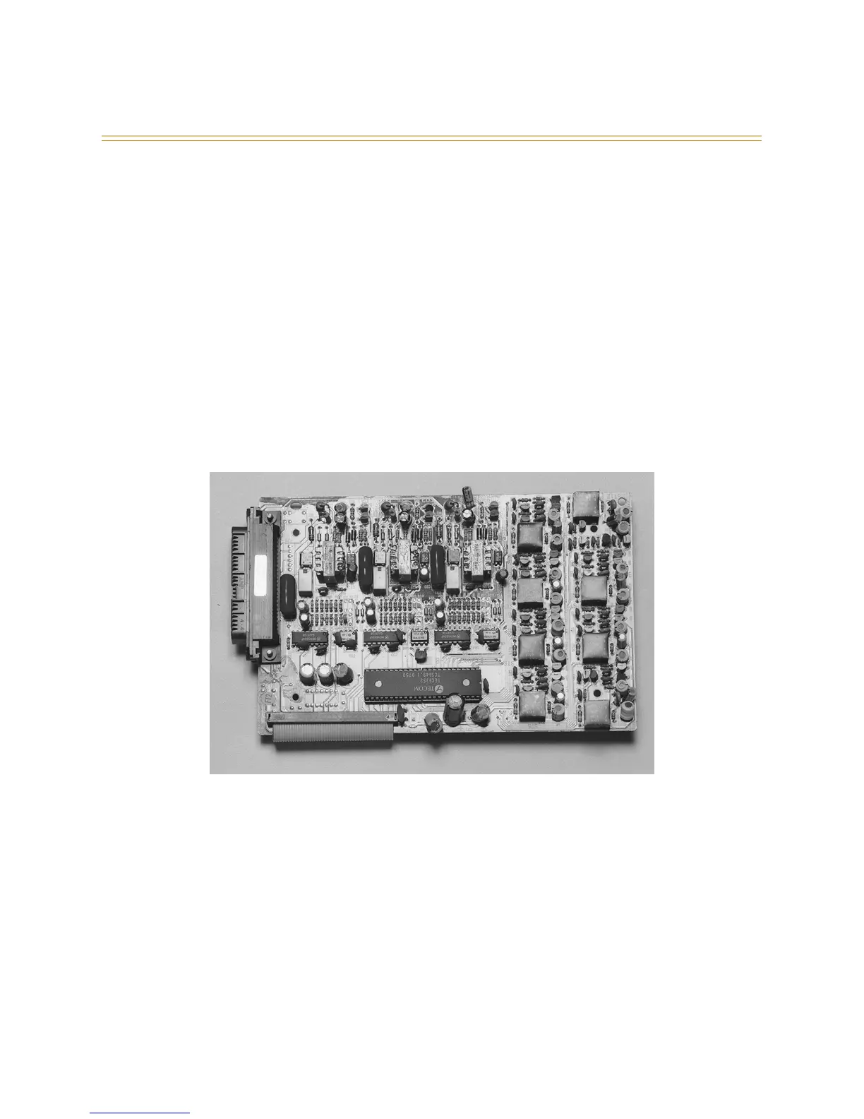
Figure 2-13: 3 x 8 Module