2-40 DHS Installation
Terminating Cables at Station Locations
At each station location, terminate station cables on 4-conductor modular jack
assemblies. Although only one pair is required for key telephone operation, the second
pair is wired through to the ADP jack for a variety of applications at the desktop. For
exception, refer to Table 2-13 .
Do not mount the modular jack assemblies on the wall at this time. They will be wall
mounted later when the station instruments are installed.
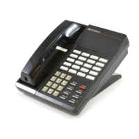
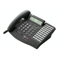
8. Key Telephones Installation
Key telephones may be mounted with three different orientations: Low Profile Desk
Mount, High Profile Desk Mount or Wall Mounted. Packaged inside each key telephone
carton are the following components:
Key telephone
Key telephone handset
7-ft. line cord
4-in. line cord (for wall mounting)
12-ft. handset cord
Small base-wedge mount assembly
Large base-wedge mount assembly
Remove the components from the carton and determine which mounting components
are required. Most telephones are installed with both mounting wedges.
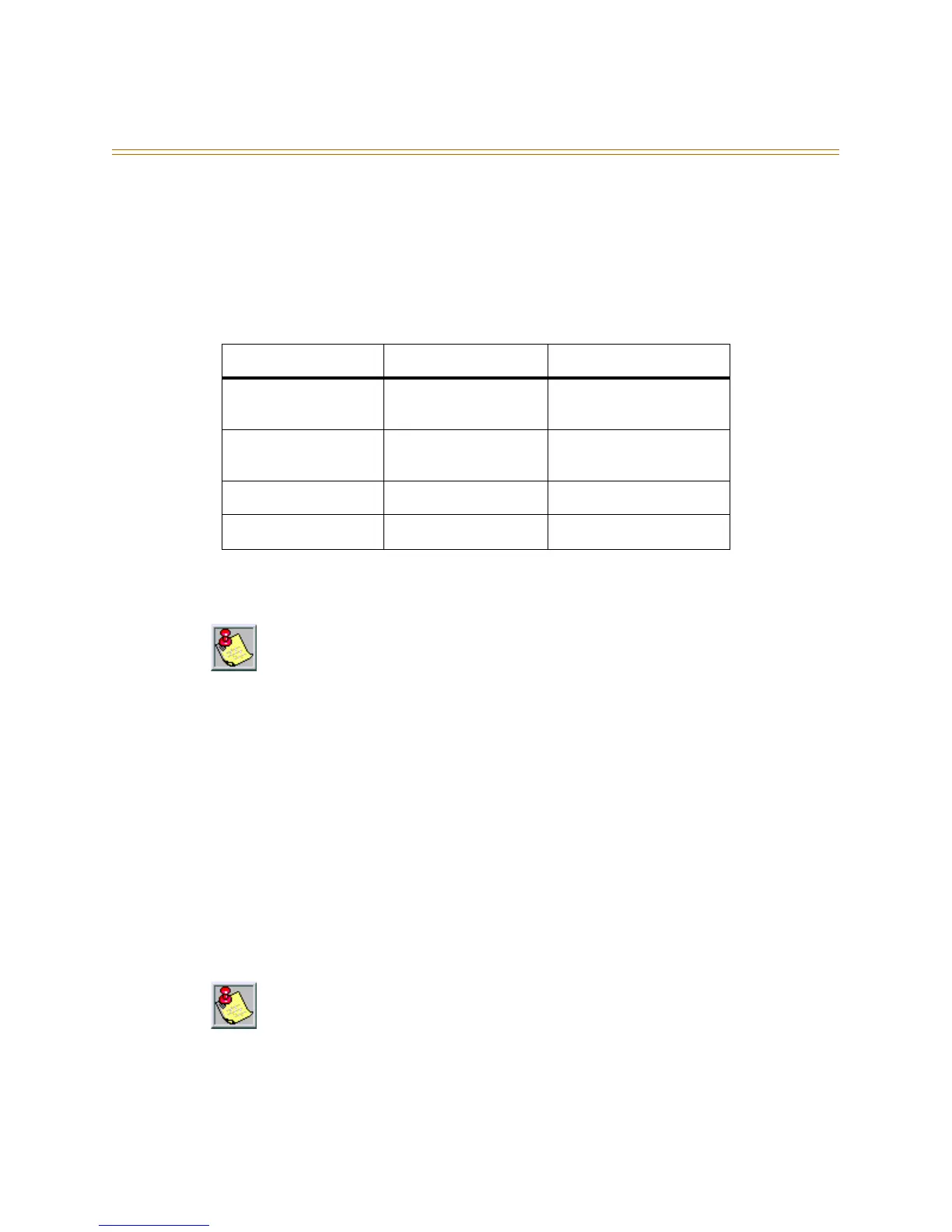
Table 2-13: Station Location Cable Terminations
Cable Conductor Jack Wire Color Designation
White/Blue Green Telephone voice and
data XT lead
Blue/White Red Telephone voice and
data XR lead
White/Orange Black ADP Jack Tip lead
Orange/White Yellow ADP Jack Ring lead
Since the digital station equipment is not polarity sensitive, reversing the digital telephone
pair has no affect on operation. The Station Interface circuits are current-limited and are
not fused.
The two wedge mount assemblies (large and small) are affixed at the factory. This
configuration is used for High Profile Desk Mounting.