2-38 DHS Installation
Conditions
It is the installer’s responsibility to assure that CO line connections are made in such a
way that proper CO Hunting will sequence from the first CO line button to the last, in
order on key telephones.
Typically, the Telco service provider provides lightning protection on the premise at
the service entrance.
Test each CO Line at the MDF for dial tone, correct ringing sequence, Telco number
assignment and polarity.
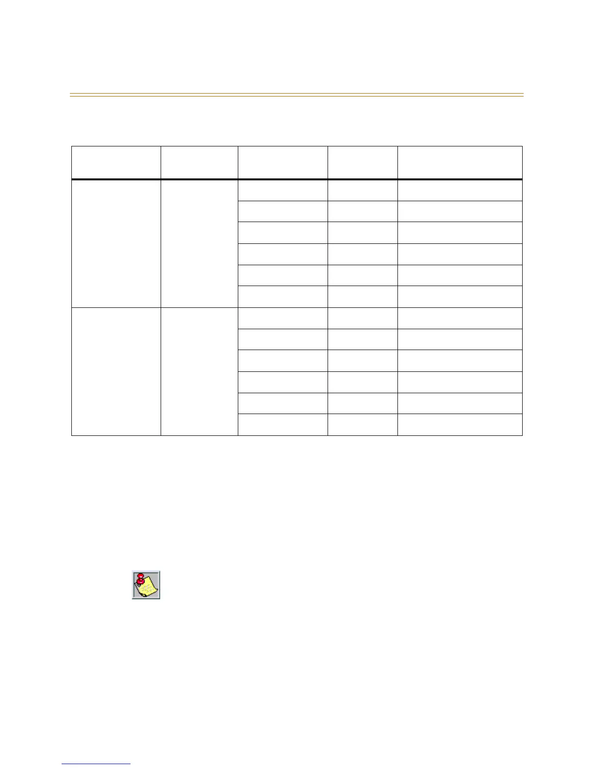
Table 2-12: CO Lines Connections, 6-Port CO Module
6-Port CO
Module Jack
Module Jack
Pin
Cable Pair
(if applicable)
Jack Wire
Color
Designation
CO (1-3) 4 White/Blue Green CO line port 1 Tip
3 Blue/White Red CO line port 1 Ring
2 White/Orange Black CO line port 2 Tip
5 Orange/White Yellow CO line port 2 Ring
1 White/Green White CO line port 3 Tip
6 Green/White Blue CO line port 3 Ring
CO (4-6) 4 White/Blue Green CO line port 4 Tip
3 Blue/White Red CO line port 4 Ring
2 White/Orange Black CO line port 5 Tip
5 Orange/White Yellow CO line port 5 Ring
1 White/Green White CO line port 6 Tip
6 Green/White Blue CO line port 6 Ring
If incoming CO lines hunt from a main telephone number and are also used for outgoing
(both-way CO line) service, always prioritize the incoming line order so that the last choice
incoming trunks appear on the higher number CO line positions. This is because the system
automatically selects idle trunks for outgoing calls, by searching from CO line 12, to CO line
11, and so on to CO line 1. This technique may avoid a head-on or glare condition where a
user trying to place an outgoing call inadvertently answers a ringing line.