DHS Installation 2-29
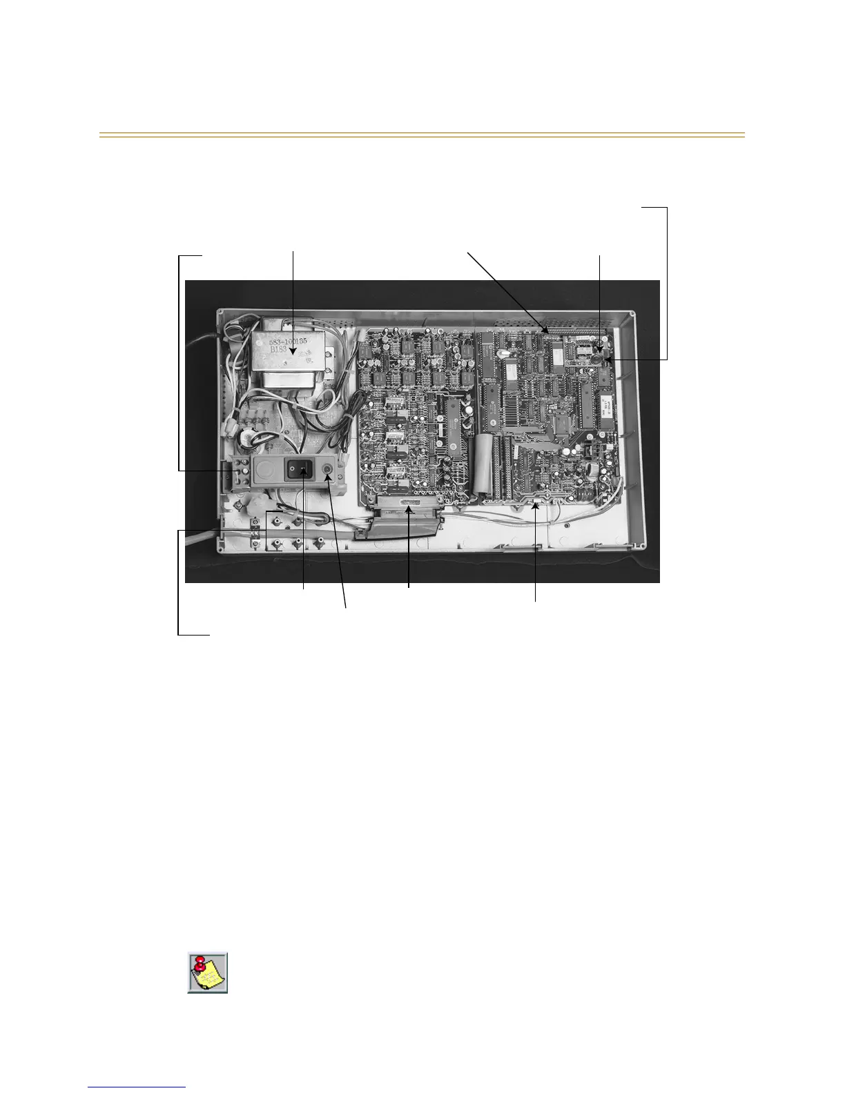
Figure 2-12: DHS Components
The cable is then routed out of the KSU through an opening at the lower left of the KSU
housing. A cable restraint clamp is provided and may be used to secure cables exiting the
KSU. The 25-pair cable is then terminated on a punch-down terminal block on the MDF.
Refer to Figure 2-19: Wiring Designations for 3 x 8 Modules.
The 3 x 8 module is installed to expand system capacity and is housed in the KSU in
stacking fashion over the initial 3 x 8 module. Three 3 x 8 modules maximum can be
installed in the KSU. The 3 x 8 module is shipped with four stand-off mounting posts.
Follow these steps when installing a 3 x 8 module:
1. Be sure that KSU power is turned OFF.
2. Remove the KSU cover.
3. Connect grounded wrist strap to a suitable earth ground.
4. Locate the screws used to secure the 3 x 8 module or 6-Port CO Module.
The 6-Port CO Module must be installed in the last available expansion bus connector on
the CPU Module. That is, if a 6-Port CO Module is installed on (JP3) a 3 x 8 module will not
function if installed on (JP4). So, if a 3 x 8 module is added after a 6-Port CO Module was
previously added, the 6-Port CO Module must be removed from (JP3), the new 3 x 8 module
installed to (JP3) and the 6-Port CO Module reinstalled onto (JP4).
AC Power
Transformer
117/230V AC
Option Module
Connector
Standard MOH
BGM Module
1/8 in. Phono Jack
for MOH/BGM
Power
Connector
System Software
Eprom socket "U9"
CPU Module
3 x 8 Module
AC Fuse
Power Switch
Power Heartbeat LED
Initialization
Switch SW1
25 Pair Champ Connector
Cable Clamp
Tie-down Posts
Spare
Fuses (2)