2-32 DHS Installation
9. Connect two 6-Conductor Line Cords into Jacks on 6-Port CO Module, and feed the
Cables through the opening in the lower left of the cabinet.
10. Mark CO Line Cords.
11. Replace the KSU cover and secure it with cover screws.
12. Restore KSU power when all wiring is complete, or continue with the installation
process.
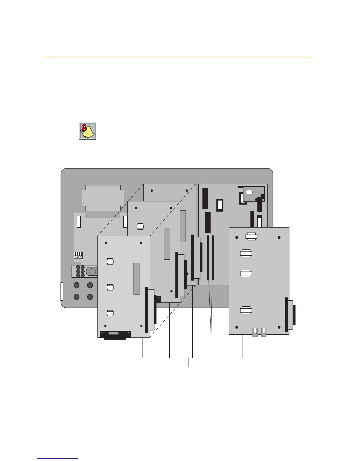
Figure 2-15: KSU Expansion Module Installation
The 6-Port CO Module must be installed in the last available expansion BUS connector on
the CPU Module. That is, if a 6-Port CO Module is installed on (JP3) a 3 x 8 module will not
function if installed on (JP4). So, if a 3 x 8 module is added after a 6-Port CO Module was
previously added, the 6-Port CO Module must be removed from (JP3), the new 3 x 8 module
installed to (JP3) and the 6-Port CO Module reinstalled onto (JP4).
AC Power Transformer
117 V AC
DC
Fuse
AC
Fuse
Cable Tie-Down
3 x 8 Standard Module
3 x 8 Expansion Module
3 x 8 Expansion Module
DC I
6 Port CO Module
CO 1-3 CO 4-6
BUS Expansion
Connectors JP3 & JP4
Three configurations are available in the DHS:
✳ 1 3 x 8 Module, and 1 6-Port CO Module,
✳ 2 3 x 8 Modules, and 1 6-Port CO Module, or
✳ 3 3 x 8 Modules