Page: 4-26
WALKER MANUFACTURING COMPANY
July 2006
SERVICE INSTRUCTIONS
PTO Shear Pin - All Models
The PTO drive shaft connection to the deck gearbox
has a shear pin to provide shock load protection to the
mower deck drive. This system provides primary
shock protection in case of blade impact and will nor-
mally shear before the individual shear bolts on the
blade hub.
When the PTO pin has sheared, use the following pro-
cedure to replace it:
1. Loosen the two bolts securing the PTO shaft guard
on the deck; lift the guard off. (Holes in guard are
slotted for easy removal.)
2. Rotate U-joint on shaft to align the shear pin hole
with the hole (and shear pin fragment) in the shaft.
Use a punch to drive the remaining portion of the
old shear pin out.
3. Install new shear pin and secure with cotter pin.
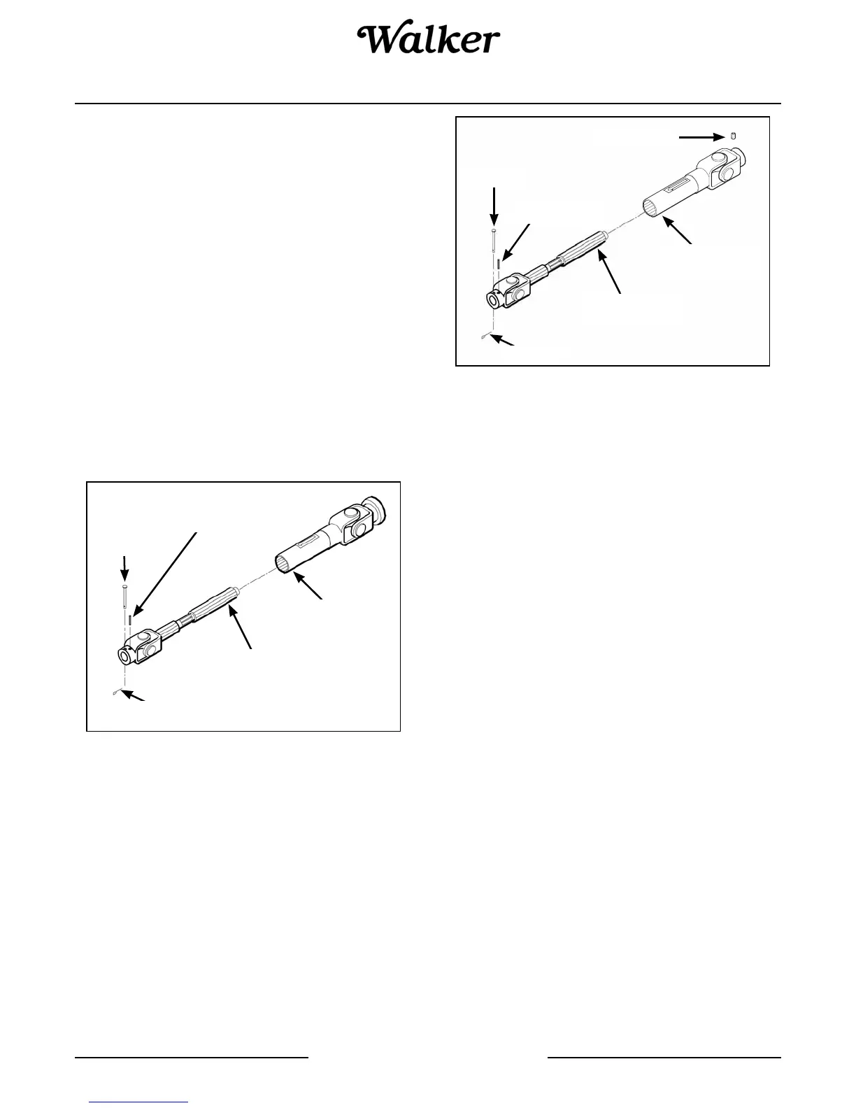
PTO Shear Pin - Model MW, MC, MD, MT, MTL
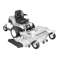
PTO Shear Pin - Model MS, MB
IMPORTANT: Use only Walker P/N 8067-13 shear
pins for replacement to provide proper shock pro-
tection -- these pins are hardened to shear under a
specific amount of load.
4. Reinstall the PTO shaft guard.
Before operating the deck, inspect the blade overload
shear bolts and also check blade timing (on gear driven
decks) by moving blades through one (1) complete
revolution. Make sure blade tips pass clear of each
other. If timing is incorrect, contact your Walker Dealer.
NOTE: Use Walker P/N 8067-10 for heavy duty gear-
boxes.
Mower Blades - All Models
Mower blades are removed and remounted as de-
scribed in Sharpen Mower Blades instructions. Dur-
ing the course of sharpening and inspecting mower
blades, if there are any of the following conditions of
wear or damage, blades should be replaced for rea-
sons of safety and performance of the machine:
• An excessive amount of the flat section of the
blade has been ground away (removed) when the
blade is sharpened. Replace the blade when less
than a 3/4 in. (19 mm) flat section remains at the
blade tip.
• Examine ends of the blade carefully, especially the
intersection where the flat section of the blade turns up
to form the “wing tip” (refer to Mower Blade Profile for
Sharpening illustration in Sharpen Mower Blades in-
structions). Since sand and abrasive material can wear
metal away in this area, the blade should be replaced
when metal thickness has worn to 1/16 in. (1.6 mm)
or less.
Cotter Pin
U-Joint
Tube Assembly
Shear Pin
Split Spring Pin
(Retains U-Joint Held on Shaft
with Broken Shear Pin)
U-Joint
Shaft Assembly
Cotter Pin
U-Joint
Tube Assembly
Shear Pin
Split Spring Pin
U-Joint
Shaft Assembly
Set Screw