Page: 4-65
WALKER MANUFACTURING COMPANY
July 2006
SERVICE INSTRUCTIONS
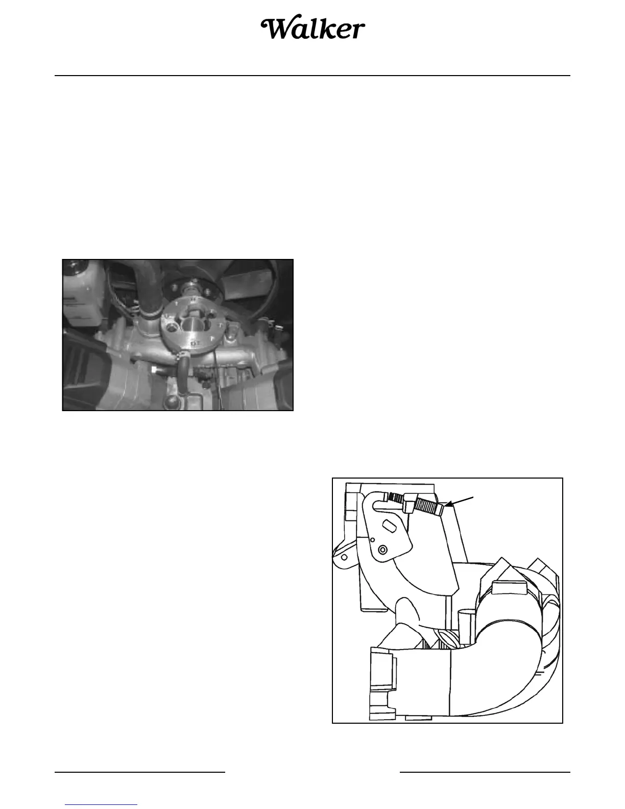
5. Reconnect the dampening spring into its governor
lever hole from the bottom. Reinstall the bushing
and reattach the throttle linkage. Refer to Throttle
Linkage/Governor Lever Connection photo.
Reattach the governor spring in the marked hole.
6. Start the engine and allow it to fully warm up and
establish closed loop operation (approximately 5-
10 min.). Check the speed settings and adjust as
necessary, first the low idle speed, and then the
high speed setting.
Throttle Body/Intake Manifold Assembly - Model
MTLEFI
Upper Intake Manifold
General
The EFI engines have no carburetor, so the throttle
function (regulate incoming combustion airflow) is in-
corporated in the intake manifold assembly. The man-
ifold consists of a one-piece aluminum casting which
also provides mounting for the fuel injectors, throttle po-
sition sensor, fuel rail, air baffle, idle speed screw, and
air cleaner assembly.
Service
The throttle body/intake manifold is serviced as an as-
sembly, with the throttle shaft, throttle plate, and idle
speed adjusting screw installed. The throttle shaft ro-
tates on needle bearings (non-serviceable), capped
with rubber seals to prevent air leaks.
Idle Speed Adjustment (RPM) - Model MTLEFI
General
The idle speed is the only adjustment that may be per-
formed on the EFI system. The standard idle speed
setting for EFI engines is 1500 RPM, but certain appli-
cations might require a different setting. Check the
equipment manufacturer’s recommendation.
For starting and warm up, the ECU will adjust the fuel
and ignition timing, based upon ambient temperature,
engine temperature, and loads present. In cold condi-
tions, the idle speed will probably be higher than normal
for a few moments. Under other conditions, the idle
speed may actually start lower than normal, but gradu-
ally increase to the established setting as operation
continues. Do not attempt to circumvent this warm up
period, or readjust the idle speed during this time. The
engine must be completely warmed up for accurate idle
speed adjustment.
Adjustment Procedure
1. Make sure there are no fault codes present in the
ECU memory.
2. Start the engine and allow it to fully warm up and
establish closed looped operation (approximately
5-10 min.).
3. Place the throttle control in the ‘‘idle/slow’’ position
and check the idle speed with a tachometer. Turn
the idle speed screw in or out as required to obtain
1500 RPM, or the idle speed specified by the
equipment manufacturer.
4. The low idle speed adjustment can affect the high
speed setting. Move the throttle control to the full
throttle position and check the high speed. Adjust
as necessary to 3750 RPM (no load), or the speed
specified by the equipment manufacturer.
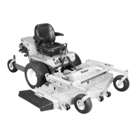
Idle Speed Screw Details
Idle Speed Screw