Page: 1-10
WALKER MANUFACTURING COMPANY
July 2006
SERVICE INSTRUCTIONS
Quick Coupler Installation Tool
Model MC, MD, MT, MTL, MTEFI
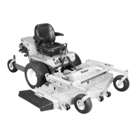
6. Raise the mower body (instead of lifting the front of
deck) and clip the counterweight springs to the re-
ceptacle on front of body. Lower the body to ten-
sion the springs. (Refer to Deck Counterweight
Spring Installation Photo.)
7. With the counterweight springs connected, the
weight on the deck caster wheels should be 15 to
25 Ib (6.8 to 11.3 kg). Check this weight by lifting
on the front of the deck carrier frame. If required,
the spring tension can be adjusted by tightening or
loosening the elastic stop nuts located underneath
the lower spring hook. Refer to Deck Counter-
weight Spring Installation photo.
Deck Counterweight Spring Installation
Deck Installation - Model MS, MB
1. Lightly grease each deck support arm (2) on the
tractor. Refer to Mower Deck Installation photo
for location of deck support arm.
2. Engage the deck carrier frame tube sockets on the
tractor support arms (refer to PTO Shaft Guard In-
stallation photo for socket location). Slide the deck
onto the support arms approximately 3 in. (76 mm).
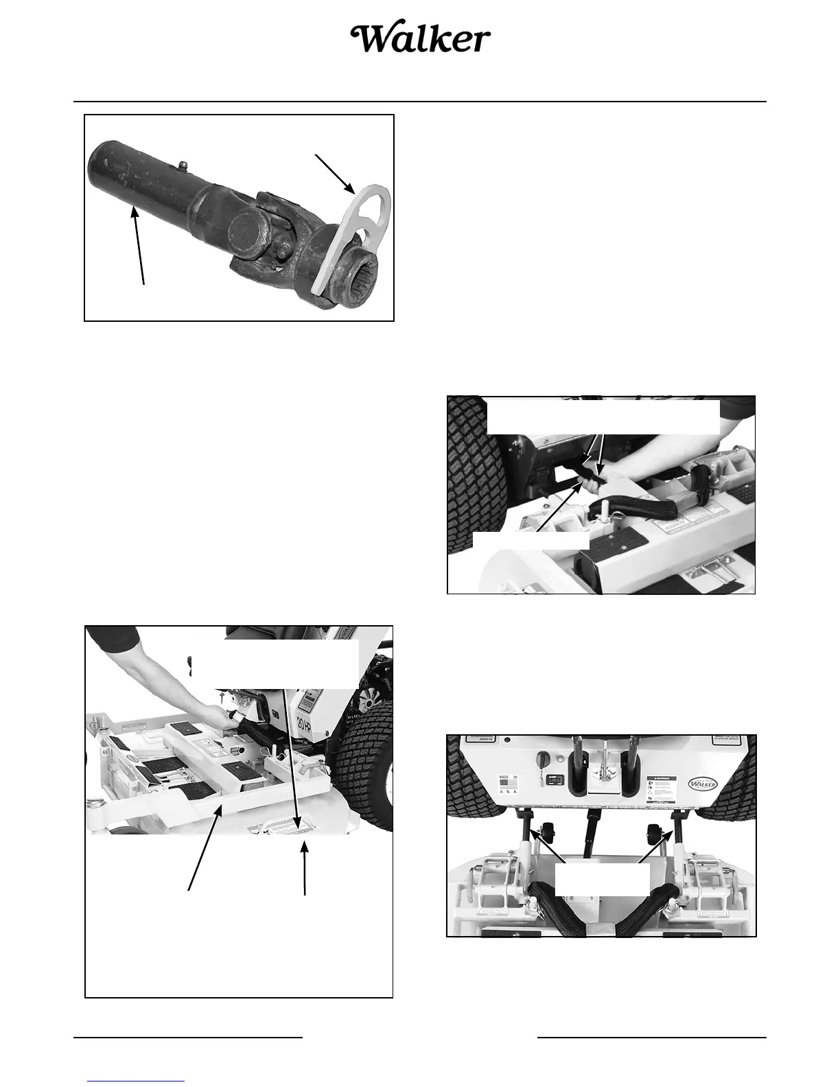
3. Align and connect the splined PTO shaft and sock-
et halves, as shown in PTO Shaft Connection
photo. The PTO shaft has a pilot end to ease align-
ment of shaft; fit shaft end into socket and rotate
shaft until the splines line up as indicated by ar-
rows, then slide together.
PTO Shaft Connection
4. Install the hitch pin through the hole on the end of
each support arm to lock the deck in place (refer to
Deck Counterweight Spring Installation photo).
Two (2) hitch pins are included in the owner's packet
of materials.
Mower Deck Installation
PTO Tube
Quick Coupler
Installation Tool
Counterweight Springs
Clip Onto Body
With Body Tilted Up
Spring Tension Adjustment
Nut Located Under Lower
Spring Hook (Not Visible)
Hitch Pins
Lock Deck On
Support Arms
PTO Connection
Arrows on Shaft and Tube
(used to align when sliding together)
Deck Support
Arms