Page: 4-46
WALKER MANUFACTURING COMPANY
July 2006
SERVICE INSTRUCTIONS
ADJUSTMENTS - ALL MODELS
Safety Switches - Model MC, MD, MT, MTL
There are three (3) safety interlock switches on the
tractor; Seat Switch, FSC Neutral - Park Switch, and
PTO Switch.
If any of the following conditions occur during starting or
operating, a safety interlock switch may be malfunction-
ing.
Slight adjustments can be made by carefully bending
the leaf switch up or down as needed.
• With an operator in the seat, the engine starts with
the Forward Speed Control (FSC) and/or the PTO en-
gaged.
• With an operator in the seat, the engine starts but
dies soon after the Forward Speed Control (FSC) or
PTO is engaged.
• Without an operator on the seat, the engine starts
and continues to run with the Forward Speed Control
(FSC) and/or PTO engaged.
• With an operator in the seat, the Forward Speed
Control (FSC) and PTO disengaged and panel horn
works, but the starter is not engaging.
Safety Switches - Model MS
There are four (4) safety interlock switches (and one
control switch if GHS equipped) on the tractor. Use the
panel nuts on the switch body to position each switch
for proper activation of the switch. The adjustment pro-
cedure for each switch is:
Seat Switch
Adjust switch position in body panel to achieve a 1/32 to
1/16 in. (.79 mm to 1.59 mm) air gap between the
switch plunger and seat frame with no weight on the
seat. Test for proper operation.
FSC Neutral-Park Switch
1. Place the FSC in NEUTRAL-PARK position.
2. Adjust switch to the point where the starter
engages when the ignition switch is turned to the
start position.
3. Adjust switch position forward an additional 1/2 to
1 turn of the panel nuts.
NOTE: If the switch cannot be adjusted forward
enough to achieve proper function, it may be nec-
essary to bend the switch mounting bracket slightly.
PTO Switch(es)
With the PTO engaged, adjust two (2) switches [three (3)
if GHS equipped] to the point of activation plus 1 or two
2 turns of the panel nuts. Normally 1/8 to 3/16 in. (3 mm
to 5 mm) of plunger travel will activate these switches.
Make sure the switches are adjusted so the actuator
plate is not bottoming out the plunger and striking the
switch body.
Tail Wheel Bearing Preload - Model MD, MT, MTL
Preload the tail wheel bearings by tightening the axle
nut until the wheel begins to tighten as it turns (not spin
freely), then loosen the nut 1/2 to 1 turn. The wheel
should spin freely without excessive end play. Lock the
axle nut with the set screw in the nut.
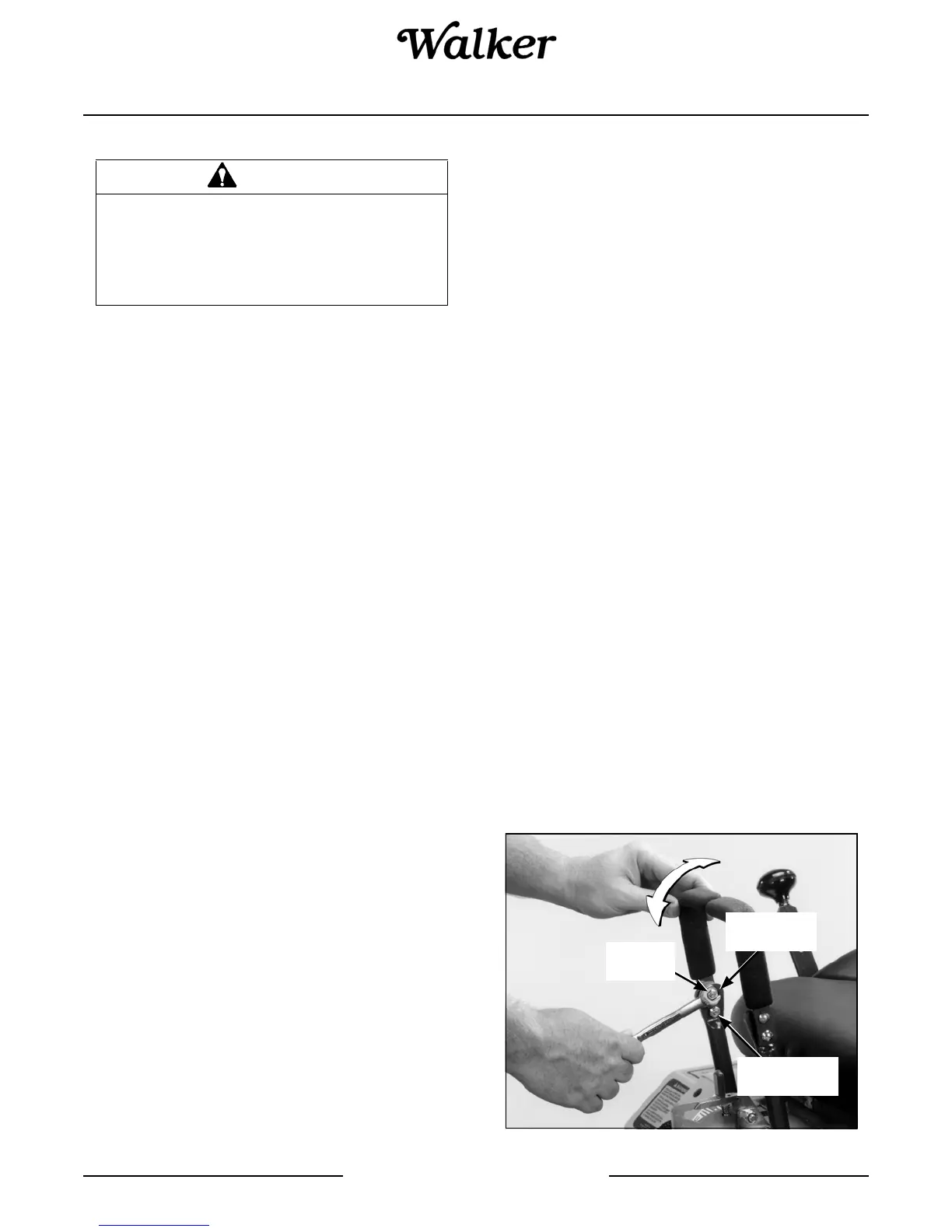
Steering Levers - Model MS, MB, MC, MD, MT
An adjustment range of approximately 3 inches is avail-
able on the steering levers - the levers can be adjusted
forward or aft depending on the arm length of the oper-
ator. The levers can be adjusted by loosening the lock-
nut at the pivot point and the locknut holding the lever in
position in the adjustment slide. Adjust levers into most
comfortable position and tighten both locknuts.
Steering Lever Adjustment
DANGER
If the engine must be running to perform
a maintenance adjustment, keep hands,
feet, and clothing from moving parts. DO
NOT wear jewelry or loose clothing.
Adjustment
Slide
Locknut
(Pivot Point)
Locknut
(Position)