Page: 1-18
WALKER MANUFACTURING COMPANY
July 2006
SERVICE INSTRUCTIONS
Implement Hitch Wiring
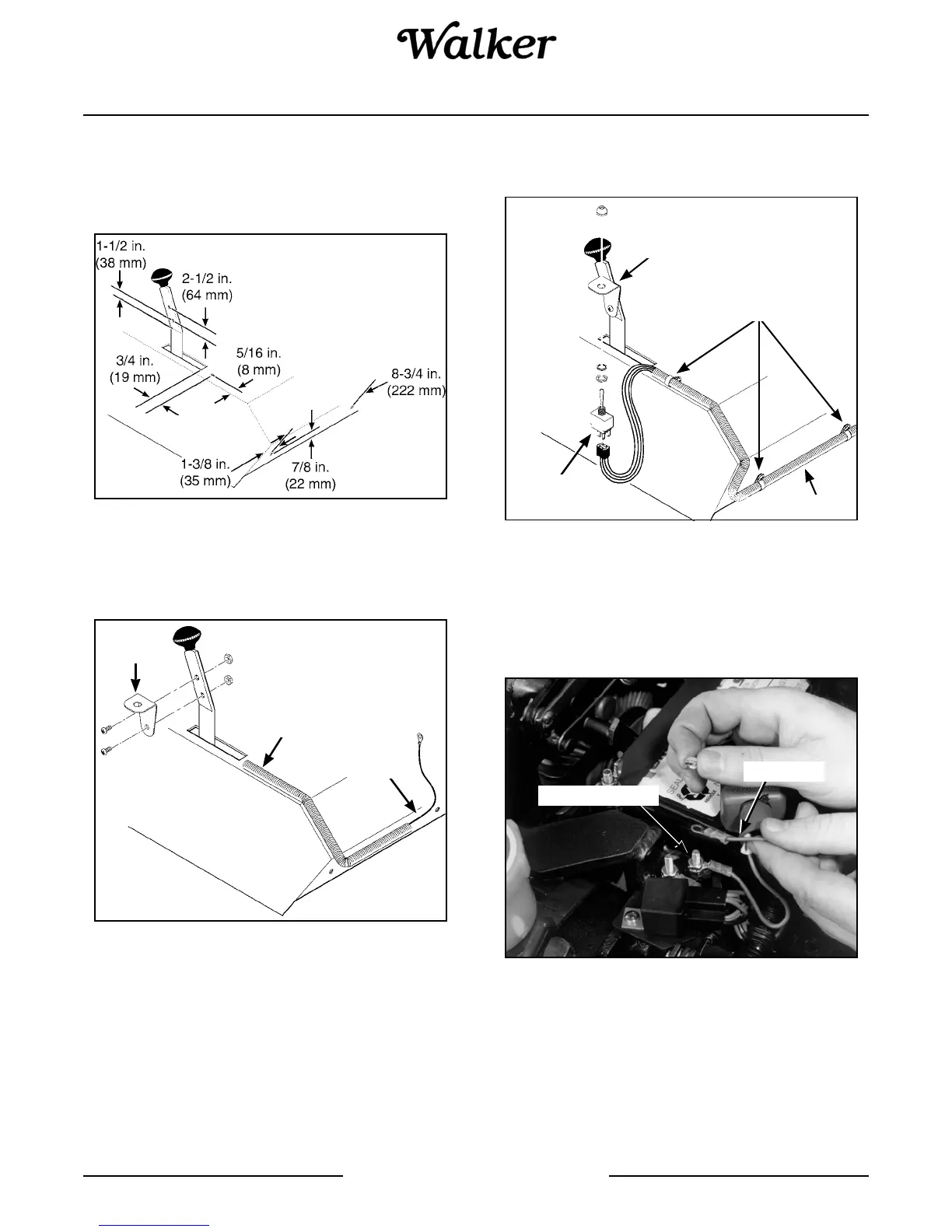
1. Drill five (5) 13/64 in. (5 mm) diameter holes in the
tractor, two in the FSC lever and three in the body,
as shown in the illustration.
Drill Holes for Implement Hitch Wiring
2. Attach the toggle switch mounting bracket on the
FSC lever using two (2) 10-24 x 1/2 in. bolts and
Keps nuts.
Attach Toggle Switch Mounting Bracket
3. Install the wiring harness to the tractor body using
the three wiring clamps, three 10-24 x 3/8 in. bolts
and Keps nuts.
4. Attach the toggle switch to the mounting bracket,
placing the switch terminals toward the front of the
mower.
Attach Wiring Harness and Toggle Switch
5. On Models MC, MDD/MDG, and MT, connect the
harness red wire to the load side of the circuit
breaker mounted on the bracket behind the bat-
tery. Connect the green ground wire to the chassis
ground bolt.
Connect Harness Wire to Circuit Breaker
IMPORTANT: For all 1987-1997 Model MC trac-
tors (with Kohler Magnum engine), connect the har-
ness red wire to the free connector of the PTO
clutch switch red wire. Refer to Implement Hitch
Wiring Diagram illustration.
Wiring
Harness
Mounting
Bracket
Ground
Wire
Mounting Bracket
Harness
Switch
Terminals
Wiring Clamps
Red Wire
Circuit Breaker