Page: 5-2
WALKER MANUFACTURING COMPANY
July 2006
SERVICE INSTRUCTIONS
ELECTRICAL SYSTEM - MODEL MT, MTL, MTEFI
For troubleshooting, refer to Wiring Diagram.
IMPORTANT: For Model MTEFI, an illuminated En-
gine Service Light on the control panel means that a
fault has been detected in the electrical/fuel system.
Contact an authorized Kohler Service Dealer to diag-
nose the fault.
IMPORTANT: Disconnect both battery cables before
unplugging any wiring connectors or making repairs on
the electrical system.
IMPORTANT: Disconnect the battery cables before
unplugging and removing the instrument panel.
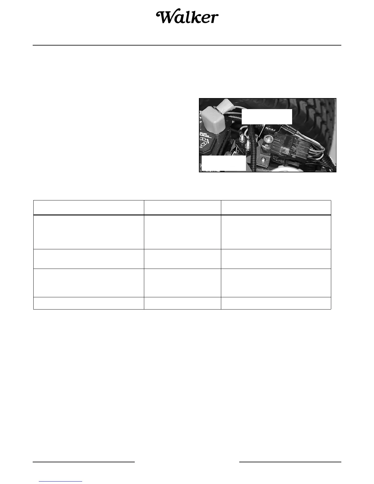
Circuit Breakers
A master circuit breaker is mounted on a bracket be-
hind the battery. The circuit breaker may have either
the manual or automatic reset function -- both types
have been used. See Circuit Breaker Location photo.
Circuit Breaker Location
30 Amp
Circuit Breaker
Circuit Breaker
Mounting Bracket
Location Reset Amperage Circuits (Electrical Load)
Master Circuit Breaker Mounted on
Bracket Behind Battery
30 AMP - Instrument Panel (MT, MTL, MTEFI)
- Headlights (MT, MTEFI)
- Starter Solenoid (MT, MTL, MTEFI)
- ECU (MTEFI)
Radiator Fan Circuit Breaker Mounted
Adjacent to Master Circuit Breaker
30 AMP - Fan Control Module (MTL)
Instrument Panel 7 AMP
- Powerfil
®
(MT, MTL, MTEFI)
- Safety Circuits (MT, MTL, MTEFI)
- Warning Lights/Horn (MTL)
Instrument Panel 10 AMP - Headlights (MTL)