Page: 4-76
WALKER MANUFACTURING COMPANY
July 2006
SERVICE INSTRUCTIONS
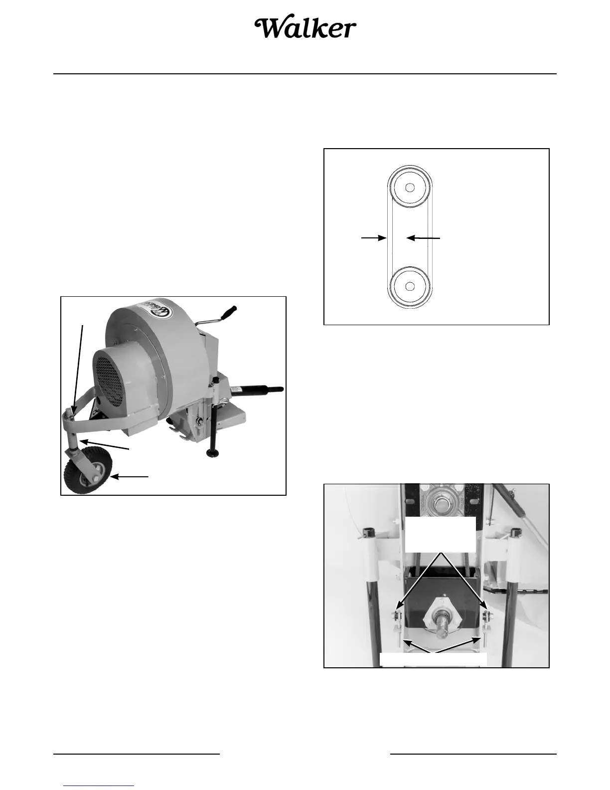
Debris Blower Front Gauge Wheel
Adjust the gauge wheel height according to surface
condition.
IMPORTANT: The air blast nozzle must clear the
ground at all times.
1. Remove the linchpin from the wheel pivot shaft.
2. Adjust wheel height by placing sleeve spacers ei-
ther on the upper or lower side of the wheel pivot
bushing. Placing the spacers on the lower side in-
creases gauge wheel height. Placing the spacers
on the upper side lowers gauge wheel height.
3. Reinstall the linchpin when proper gauge wheel
height has been reached.
Gauge Wheel Height Adjustment
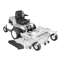
Debris Blower Drive Belt Tension
The drive belt deflection must be 1/8 in. (3 mm) when 6-
1/2 to 9 lbf (29 to 40 N) is applied midway between the
two pulleys.
Proper Drive Belt Deflection
1. Remove the belt guard from the debris blower
housing by removing the two (2) cover pins and
hairpins securing it to the housing.
2. Loosen the two (2) nuts and bolts on the blower
pulley bearing support and turn the adjustment
nuts on each side until the required tension is
reached. Tighten the fasteners securely and rein-
stall the belt guard by reversing the removal proce-
dures.
Drive Belt Tension Adjustment
Gauge Wheel
Pivot
Bushing
Linchpin
1/8 in. (3 mm)
6.5 to 9 lbf
(29 to 40 N)
Adjustment Eye Bolts
Blower Pulley
Bearing
Support Bolts