Page: 1-17
WALKER MANUFACTURING COMPANY
July 2006
SERVICE INSTRUCTIONS
Implements
Walker Implements are shipped partially assembled.
After uncrating the implement adaptor and/or imple-
ment(s), initial setup is required.
NOTE: During the process of unpacking, any dam-
aged or missing parts should be noted and reported to
the delivering carrier immediately (put in writing within
15 days). The carrier will provide directions for pro-
ceeding with a claim to receive compensation for dam-
age.
IMPLEMENT HITCH
Implement Hitch Installation
1. Remove the mower deck from the tractor if neces-
sary. Refer to the appropriate Tractor Owner’s
Manual.
2. Lightly grease each tractor support arm (2) on the
tractor. Refer to Implement Hitch Installation
photo for location of tractor support arms.
3. Engage the hitch frame tube sockets on the tractor
support arms. Slide the implement hitch onto the
support arms approximately 3 in. (76 mm).
4. Install the hitch pin through the hole on the end of
each support arm to lock the hitch in place. Two (2)
hitch pins are included in the owner’s packet of ma-
terials.
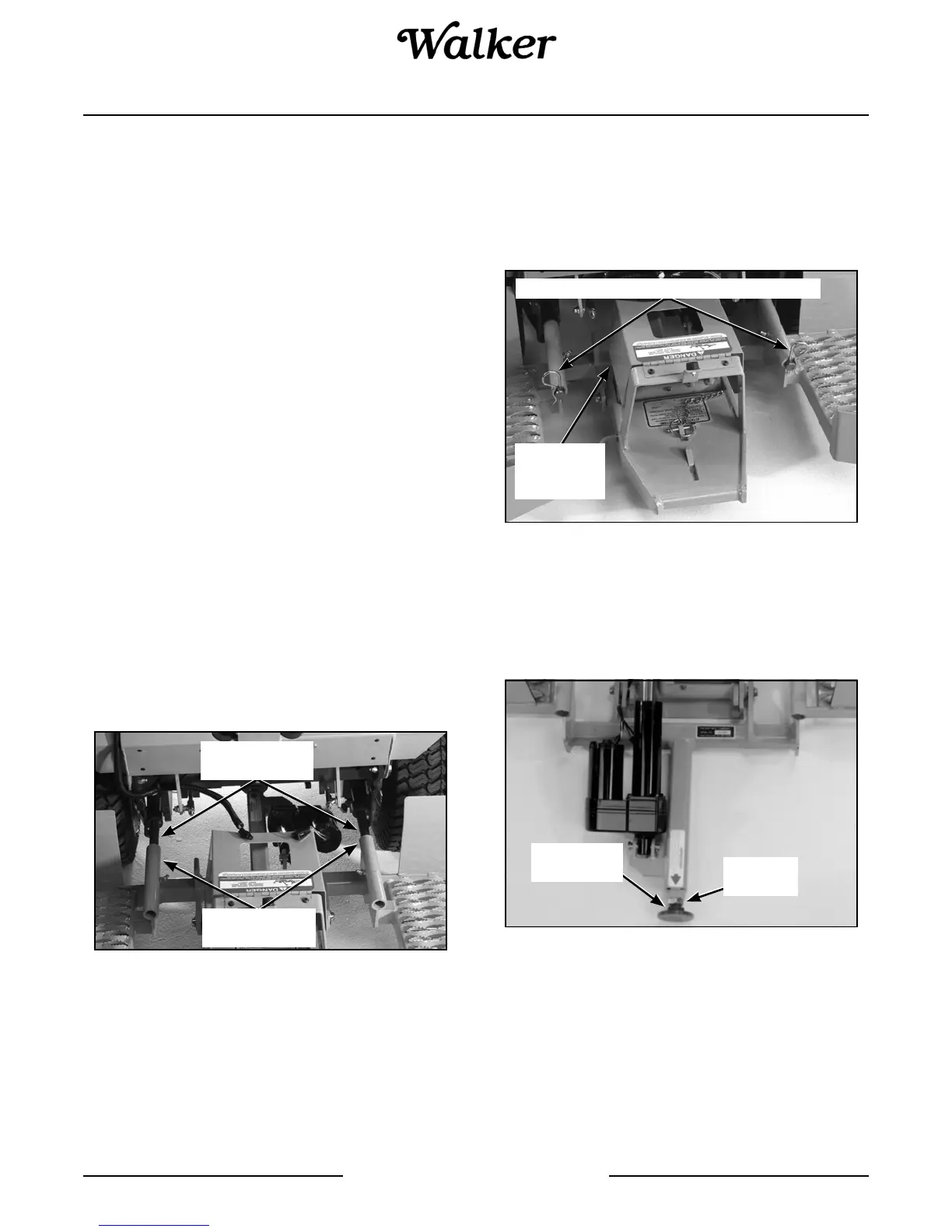
Implement Hitch Installation
IMPORTANT: If the tractor body needs to be
raised, the PTO shield must be in the closed or
down position and the implement must be in the
lowered position. The only time the PTO shield
needs to be open or raised is when connecting or
disconnecting the driveline for the rotary broom,
snowblower, or debris blower.
PTO Shield in CLOSED Position
5. Loosen the 3/4-10 jam nut on the end of the imple-
ment Hitch. Adjust the 3/4-10 x 2 in. hex bolt until
deck support arms are parallel with ground. Se-
curely tighten the 3/4-10 jam nut to prevent the bolt
from moving.
Implement Hitch Jam Nut Adjustment
IMPORTANT: This adjustment will need to be
made only once if the same tractor and hitch are
used together. If the hitch will be used on more than
one tractor, this adjustment will be required every
time the hitch is mounted on a different tractor.
Grease Tractor
Support Arms
Hitch Frame
Tube Sockets
Hitch Pins Lock Hitch on Support Arms
PTO Shield
in CLOSED
Position
3/4 - 10
Jam Nut
3/4 - 10 x 2"
Hex Bolt