Page: 4-59
WALKER MANUFACTURING COMPANY
July 2006
SERVICE INSTRUCTIONS
Forward Speed Control Friction Lock - Model MS,
MC, MD, MT
The FSC friction lock is adjusted to hold the selected
forward speed when the steering levers are moved
and yet the friction is not too heavy to make moving
the control difficult (too much friction). The proce-
dure for checking and adjusting the FSC friction lock is
as follows:
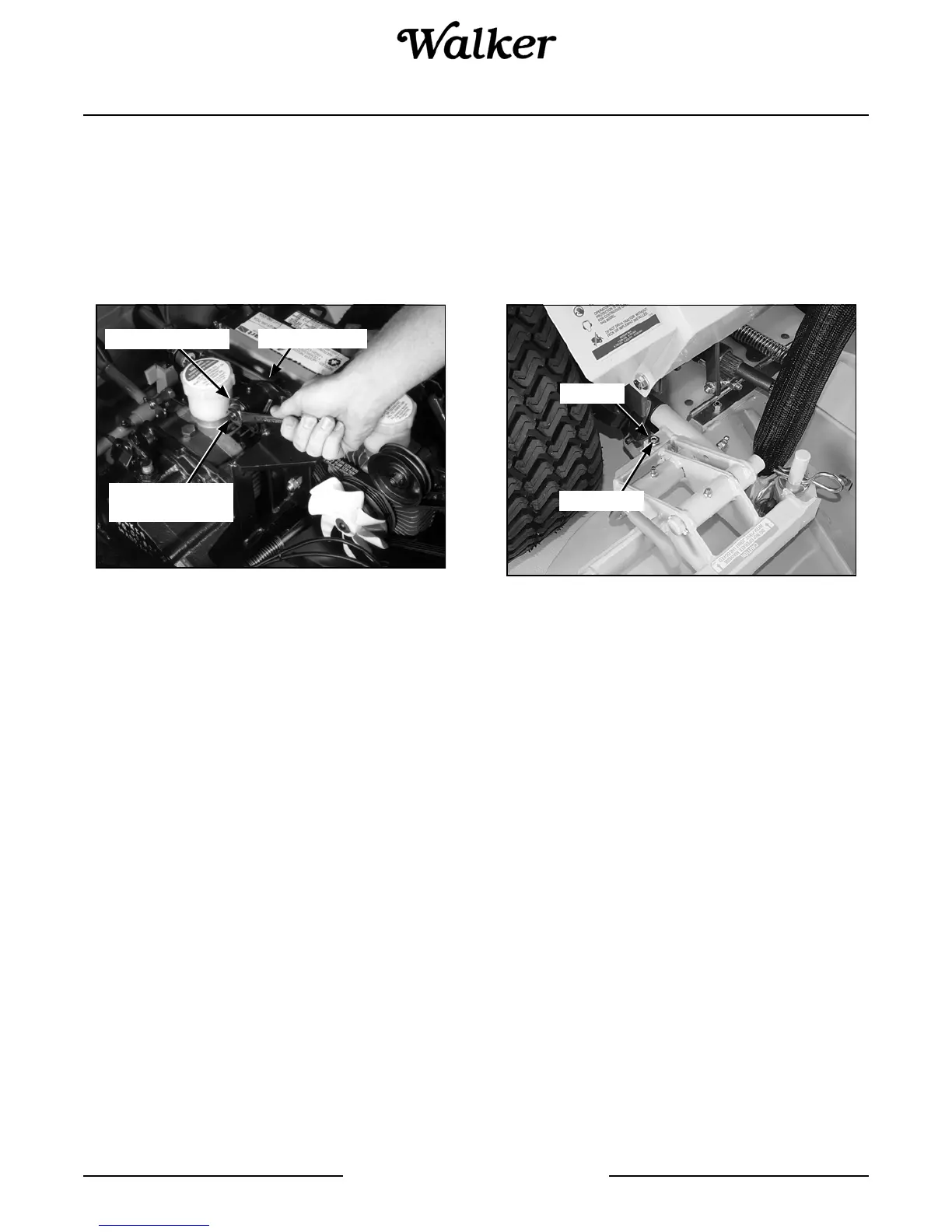
Forward Speed Control Friction Lock
1. Place the FSC in the full FORWARD position and
pull both steering levers back; the FSC lever
should not move. If the FSC lever moves back
when the steering levers are pulled back, the fric-
tion needs to be increased.
2. With the steering levers held back, move the FSC
lever back from the FORWARD position. With a
proper amount of friction adjusted, the FSC lever
should move back with a slight amount of resis-
tance (friction). If the FSC lever movement is “stiff”,
the friction needs to be decreased.
3. The FSC friction is increased or decreased by
tightening or loosening the friction adjustment
nut. Loosen or tighten the nut and check the con-
trol function until conditions of both steps 1 and 2
(above) are met.
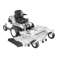
Tilt-Up Deck Adjustable Stop - All Decks
When the carrier frame hinge joint is properly adjusted,
the deck lock levers should move in and out of the en-
gaged and disengaged positions freely. Adjustments
are made by loosening the jam nut and tightening or
loosening the set screws on the Deck Mount Pivot
Brackets. Retighten the jam nut when the adjustment is
complete.
Tilt-Up Deck Adjustable Stop
Fuel Valve Solenoid Linkage - Model MD
To prevent damage to the fuel valve solenoid, the link-
age to the engine must be adjusted so the solenoid bot-
toms out before the control arm on the engine contacts
its stop (when the engine is running). A solenoid that
does not bottom out when the engine is running will be-
come overloaded and burn out.
IMPORTANT: The solenoid linkage should be
checked and adjusted any time the solenoid is removed
and replaced (either reinstalling an existing solenoid or
installing a new replacement).
Check and adjust the solenoid linkage as follows:
1. Manually pull the fuel valve open and check the
gap between the control arm on the injector pump
and the stop. The required gap is approximately
1/16 in. (1.6 mm).
Friction Washer
Friction
Adjustment Nut
FSC Actuator
Set Screw
Jam Nut