Page: 4-67
WALKER MANUFACTURING COMPANY
July 2006
SERVICE INSTRUCTIONS
Checking ‘‘Split’’ of Clamp
2. Follow the instructions in Step 2 of Checking the
Initial Adjustment, then reattach the throttle linkage
to the governor lever with the bushing clip. It is not
necessary to reattach the damper or governor
springs at this time.
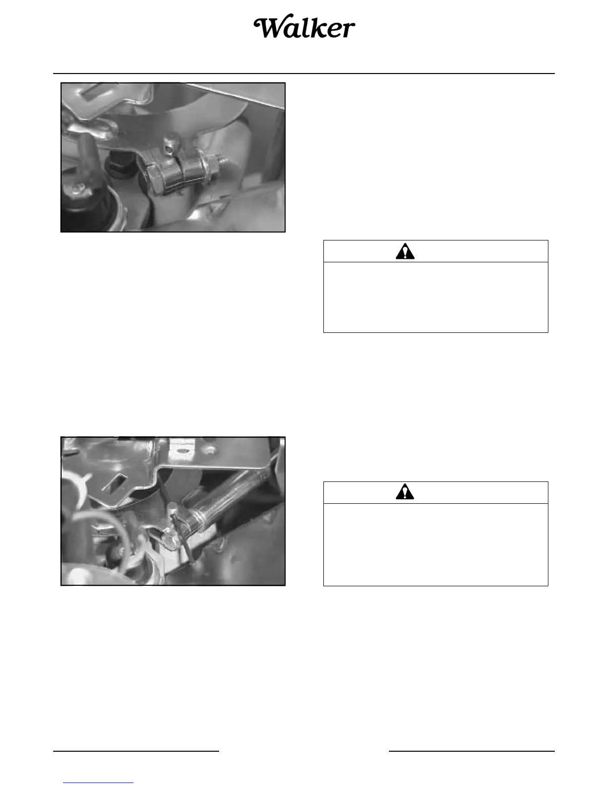
3. Insert a nail into the hole in the top of the
crossshaft. Using light pressure, rotate the gover-
nor shaft counterclockwise as far as it will turn,
then torque the hex nut on the clamping screw to
6.8 N·m (60 in. lb.). Refer to Adjusting Governor
Shaft photo. Make sure that the governor arm has
not twisted up or down after the nut has been tight-
ened.
Adjusting Governor Shaft
4. Verify that the governor has been set correctly.
With the linkage still retained in the “Full Throttle”
position (Step 2), unsnap the bushing clip, sepa-
rate the linkage from the bushing, and remove the
bushing from the lever. Follow Steps 3 and 4 in
‘‘Checking the Initial Adjustment’’.
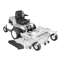
5. Reconnect the dampening spring into its governor
lever hole from the bottom. Reinstall the bushing
and reattach the throttle linkage. Refer to Throttle
Linkage/Governor Lever Connection photo.
Reattach the governor spring in the marked hole.
6. Start the engine and allow it to fully warm up and
establish closed loop operation (approximately 5-
10 min.). Check the speed settings and adjust as
necessary, first the low idle speed, and then the
high speed setting.
Carburetor - Model MS
Carburetor adjustments are required to compensate
for differences in altitude, temperature, and fuel.
Once the carburetor has been set, no further adjust-
ments should be required. However, if the engine
exhibits any of the following symptoms, the carburetor
adjustment should be checked: black, sooty exhaust
smoke, lack of power, engine miss or backfire, hard to
start, rough running or idle.
NOTE: Also refer to the Kawasaki Service Manual for
detailed carburetor adjustment information.
NOTE: The air cleaner and air intake hose must be
connected to the carburetor when adjusting the
carburetion.
The carburetor main jet is fixed (non-adjustable). For
operation above 5,000 ft (1,524 m) above sea level, the
carburetor main jet should be changed for best fuel
economy and power. Contact an authorized Kawasaki
engine dealer to change the carburetor main jet.
CAUTION
DO NOT change the engine governor set-
tings or overspeed the engine. The gov-
ernor has been factory-set for maximum
safe engine operating speed.
CAUTION
ALWAYS use the proper engine service
manual when working on the engine. Un-
authorized maintenance operations or
modifications to the engine MAY result in
unsafe operating conditions.