Page: 1-16
WALKER MANUFACTURING COMPANY
July 2006
SERVICE INSTRUCTIONS
Implement Assembly
SETUP INSTRUCTIONS
Perfaerator
The PERFAERATOR™ is shipped partially assembled.
After uncrating, initial setup is required.
NOTE: During the process of unpacking, any dam-
aged or missing parts should be noted and reported to
the delivering carrier immediately (put in writing within
15 days). The carrier will provide directions for pro-
ceeding with a claim to receive compensation for
damage.
Lift Lever Installation
The lift lever for the camshaft assembly position is par-
tially assembled. Stand the lift lever upright and attach
the remaining hardware.
Install Lift Lever Handle
(stand upright and insert hardware)
Installation on Tractor
1. Remove the mower deck from the tractor if neces-
sary. Refer to the appropriate Tractor Owner's
Manual.
2. Lightly grease each tractor support arm (2) on the
tractor.
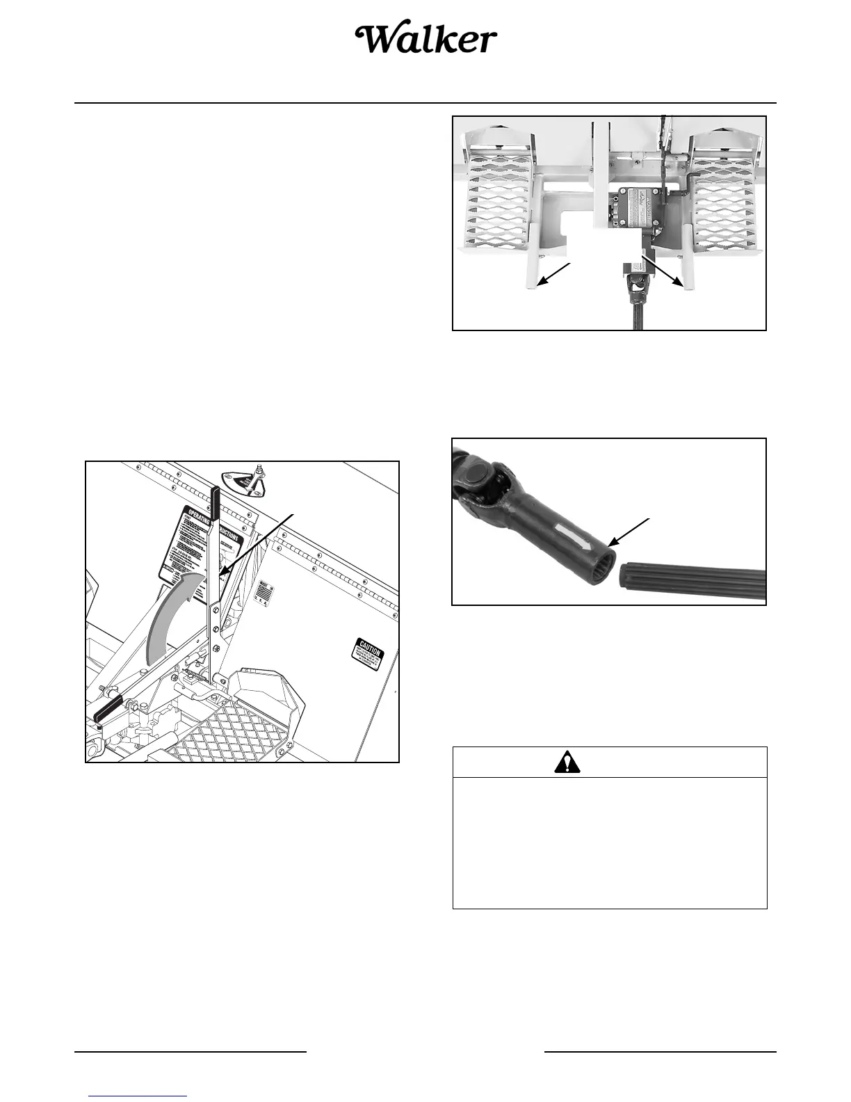
Attach Aerator to Tractor
3. Engage the aerator frame tube sockets on the trac-
tor support arms. Slide the implement hitch onto
the support arms approximately 3 in. (76 mm).
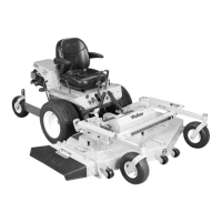
Connect Driveline Coupler to Tractor PTO
4. Connect the aerator driveline to the tractor PTO
shaft by sliding back the locking collar on the yoke,
then push the yoke over the PTO shaft until the
locking collar snaps back fully. Make sure the
driveline is well secured at both ends.
5. Install the hitch pin through the hole on the end of
each support arm to lock the hitch in place. Two (2)
hitch pins are included in the owner’s packet of ma-
terials.
Lift Lever
DANGER
This shaft turns at very high RPM. If the
collar is not locked to the PTO shaft at the
tractor end, or if the yoke at the aerator
end is not secured properly, the driveline
can fly loose with great force capable of
causing serious injury or death.
Mounting
Tubes
Only use PTO U-Joint
Tube P/N 7275-15
(9.06" OAL)